|
<< Click to Display Table of Contents >> Bezier cross section |
  
|
|
<< Click to Display Table of Contents >> Bezier cross section |
|
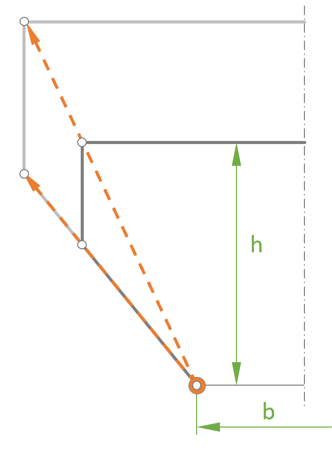
The shape of a Bezier cross-section is described by a Bezier curve.
One half of the shape of the cross-section is described using a 4th degree Bezier polynomial. •Points 0 and 4 are the end points and cannot be changed. •Point 1 can be moved along a straight line which corresponds to the cone angle of the cross-section (0° for a rectangle type, δ for a trapezoid type). •Point 3 can only be moved on a straight line specified by the cone angle λ. •Point 2 can be moved freely and therefore has the major influence on the shape of the cross-section.
|
|
Two basic shapes of the cross-section can be selected, rectangular or trapezoid.
With Inner point position, you can select whether positioning of the inner points 1 and 3 should be relative (0..1: 0 = point 0/4; 1 = point S) or absolute (distance from point S), where S is the intersection point of lines 0-1 and 4-3.
The numeric values of the positions can be changed by right-clicking on points 1 or 3.
The scaling center point is the left (right) inlet point, which is not located on the section center line. |
|