|
<< Click to Display Table of Contents >> Blade profiles |
  
|
|
<< Click to Display Table of Contents >> Blade profiles |
|
► Impeller | Blade properties ![]()
[ Axial machines only ]
On tabsheet Profile selection the axial blade profile properties are specified. To this end the profiles have to be selected from the Profile manager.
|
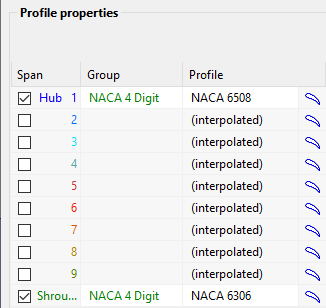
Profile specification on 1 span position is necessary at least to use the same profile on all spans. Alternatively on any other span position deviating profiles can be selected resulting in interpolation between different profiles. Profile selection per span can be activated by selecting the check-box at the beginning of each line. |
In general, two alternative methods for airfoil design are available:
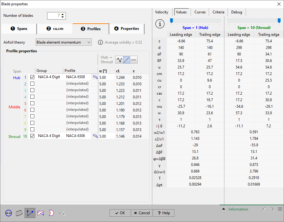
Here either NACA 4 digit or point based profiles can be used. Also an angle of attack α has to be specified, see blade element momentum method.
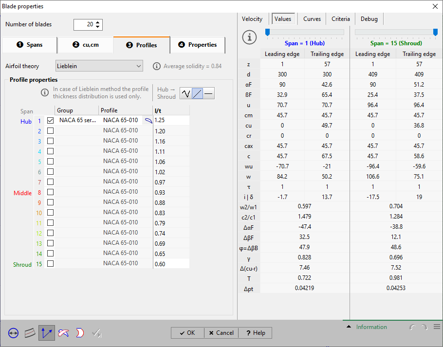
Here only profiles of the NACA 65 series can be used. A solidity l/t has to be specified that has to be between 0.4 and 2.0 on all spans. It is used for the calculation of the skeleton length and stagger angle, see Lieblein method.
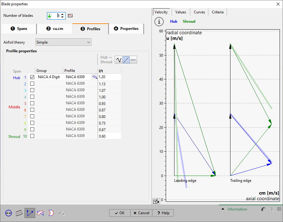
Here either NACA 4 digit or point based profiles can be used. A solidity l/t has to be specified, see simple method.
Problem |
Possible solutions |
|---|---|
Profile is not reasonable. |
|
Geometric description or polar data not reasonable. |
NACA 4 digit or Point-based: Polar data must have more than one pair of (cl, α) and (ε, α), see Profile manager. Point-based: the mid of upper and lower side must start at (0, 0) and end at (1, 0) resp. NACA 65 series: Thickness value count must be bigger than one. Circular: must have more than 2 data points (x, y). |