|
<< Click to Display Table of Contents >> Blade properties |
  
|
|
<< Click to Display Table of Contents >> Blade properties |
|
► IMPELLER | Blade properties ![]()
Definition of blade properties is made in three steps:
(1) Spans
(2) Cu-specification
(4) Kinematics
|
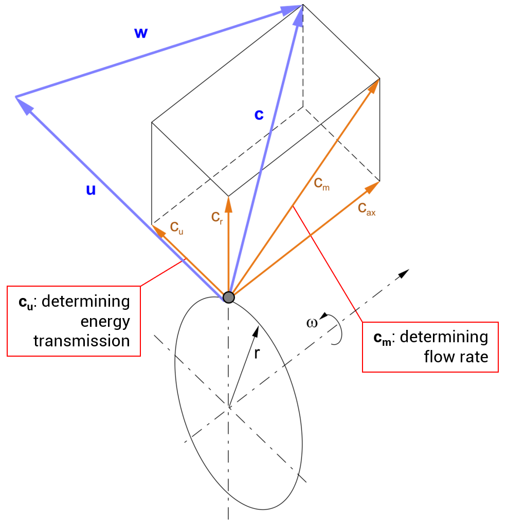
Fundamental kinematic equation |
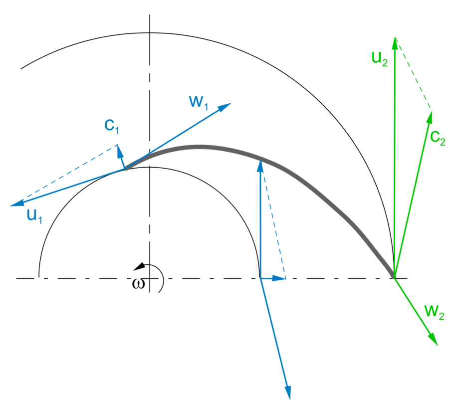
Radial impeller |
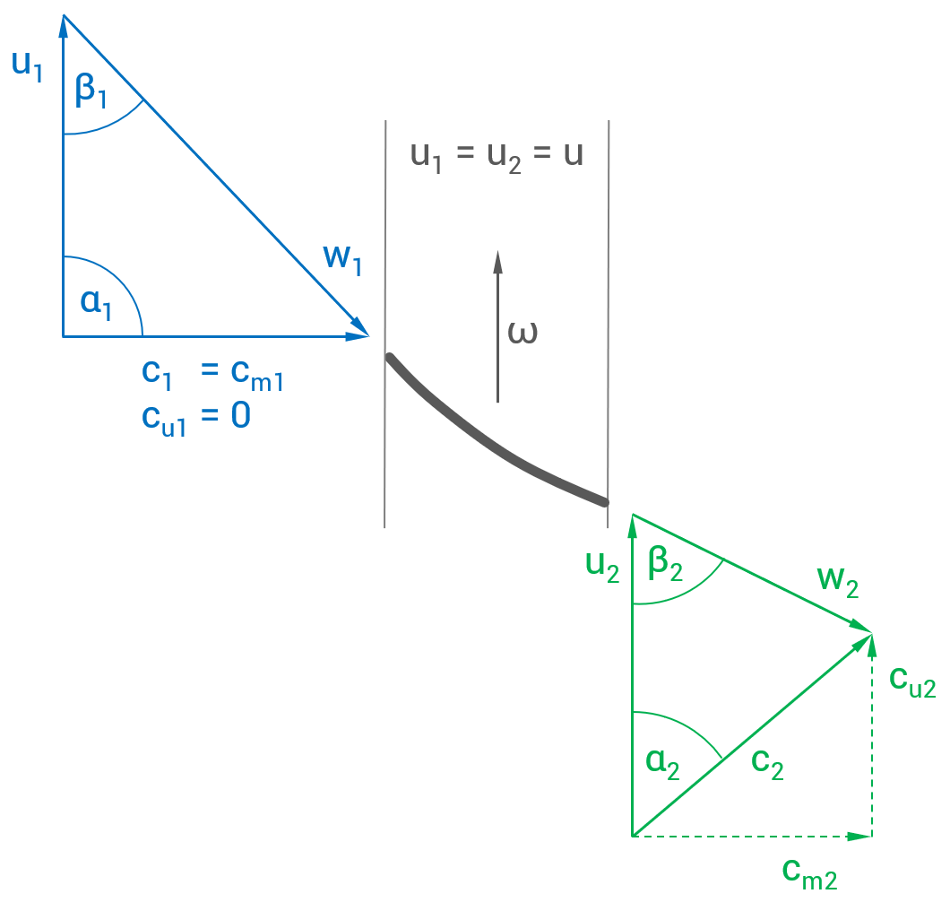
Axial impeller |
|
|
![]()
In the right panel some information are displayed which result from calculated or determined values:
|
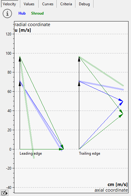
(1) Velocity trianglesThe velocity triangles of inflow and outflow are displayed. Continuous lines represent flow velocities on hub (blue) and shroud (green). Velocities directly before and behind blade area are displayed by dashed lines to show the influence of blockage in the flow domain. Furthermore the blade angles are displayed by thick lines in order to see the incidence angle on the leading edge and the flow deviation caused by slip velocity on trailing edge. |
||||||||||||||||||||||||||||||||||||||||||||||
|
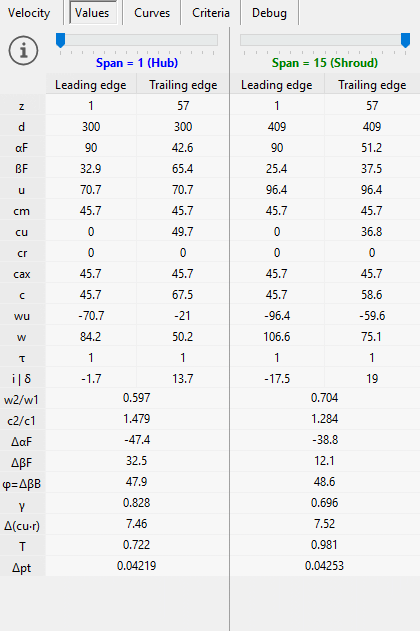
(2) ValuesNumerical values of velocity components and flow angles are displayed in a table. The track bar on top of table can be used to get the values at any span. A short description is at mouse cursor too:
|
||||||||||||||||||||||||||||||||||||||||||||||
|
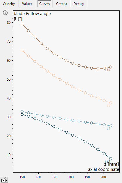
(3) CurvesHere blade angles as well as relative flow angles are displayed versus span. Progressions of geometric parameters (angles):
|
||||||||||||||||||||||||||||||||||||||||||||||
|
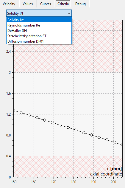
(4) CriteriaProgressions of aerodynamic and airfoil parameters:
|
Problem |
Possible solutions |
|---|---|
Automated blade angles are active. |
|
Stagger angles and chord length are updated automatically when input parameters are modified. |
To fix stagger angles and chord length uncheck "Automatic" calculation. Then calculation must started manually if required. |
Automated blade angles are NOT active. |
|
Stagger angles and chord length are not updated automatically if any input parameters are modified. |
To be sure that all parameter modifications are considered you could switch to an automatic calculation by checking the "Automatic" option. |
Swirl gradient violates Euler equation. |
|
cu2*r2 is lower than cu1*r1 (turbines: cu2*r2 is higher than cu1*r1) resulting in energy transmission in the wrong direction (Euler equation of turbomachinery). |
Recalculate and/or check stagger angles γ and chord length l, check cu-cm-specification or chosen profiles. |
ΔβB1/2 (leading/trailing edge) = ... is larger than warning level of ... |
|
Blade angle difference (highest - lowest value) at all spans exceeds the warning level (see Preferences: Warning level). |
Check the resulting 3D blade shape and avoid high blade angle differences on spans if possible. |
ΔβB (span) = ... is larger than warning level of ... |
|
ΔβB = |βB2 - βB1| on one or more spans exceeds the warning level (see Preferences: Warning level). |
Check the resulting 3D blade shape and avoid high blade angle differences between leading and trailing edge if possible. |
Blade angles βB1/2 cannot be determined. Thermodynamic state could not be calculated. Check main dimensions, meridional shape or global setup. [ for compressors and turbines only ] |
|
The dimensions or meridional contour might be too tight for the specified mass flow and inlet conditions. |
Increase the dimensions (width etc.), meridional contour or change the Global setup (e.g. decrease mass flow). |