|
<< Click to Display Table of Contents >> Global setup |
  
|
|
<< Click to Display Table of Contents >> Global setup |
|
► PROJECT | General | Global setup ![]()
Here the global project settings are defined valid for all components.
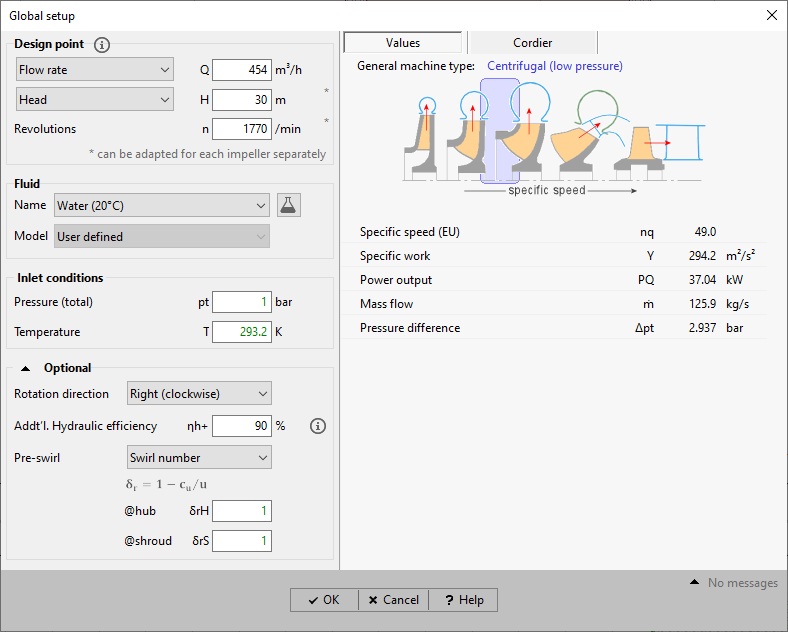
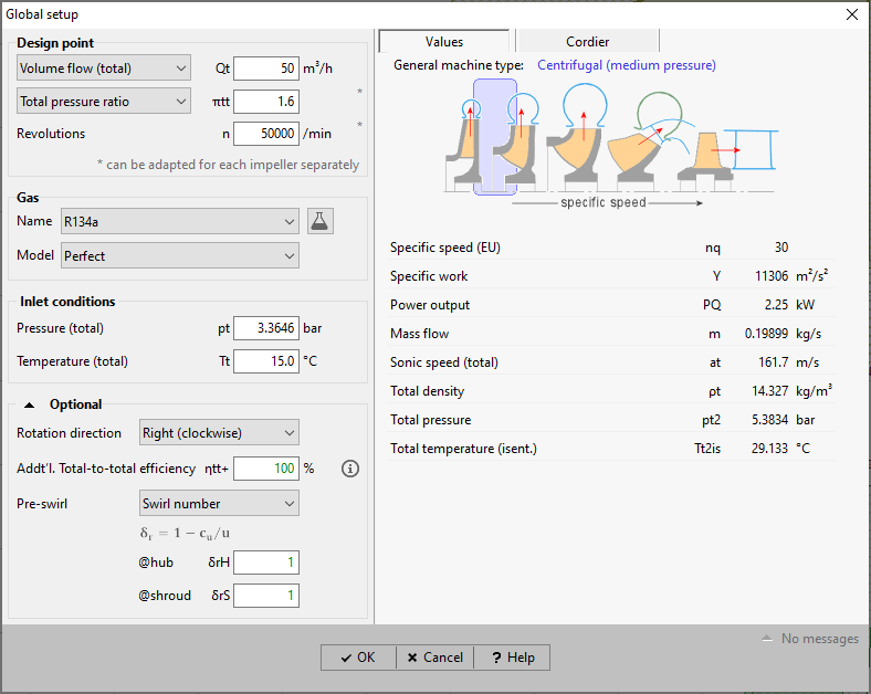
Depending on the project type different input parameters are required (see below). As examples you see the Global setup dialog for pumps on the left side, for compressors on the right side.
|
|
Here you have to enter the design point data: (1) Flow rate: •for pumps, fans, hydro turbines: volume flow Q or mass flow ṁ •for compressors: mass flow ṁ or volume flow Q (referring to total state on suction side) •for gas turbines: mass flow ṁ (2) Energy transmission: •for pumps: head H or total pressure difference Δpt •for fans: total pressure difference Δpt •for compressors: total pressure ratio πt or total pressure difference Δpt or specific work Y •for gas turbines: total pressure ratio πtt or total-to-static pressure ratio πts •for hydro turbines: head H (3) Number of revolutions n |
|
Energy transmission and number of revolutions can be specified separately for each impeller in the project, see Main dimensions.
The sum of energy transmissions of all impellers in multi-stage machines should be equal to the Global Setup value.
Here the fluid has to be defined.
One has to select one of the predefined fluids. The list of existing fluids can be modified in the Fluid manager.
For compressors and turbines the gas model has to be specified additionally: Perfect, Redlich-Kwong, Aungier/ Redlich-Kwong, Soave/ Redlich-Kwong, Peng-Robinson or CoolProp.
For pumps the fluid properties can be determined by using the CoolProp library if the fluid is listed there. If this is not the case the model User defined is available only, i.e., a constant density is applied.
Here the total state at the inlet - total pressure pt and total temperature Tt - has to be defined. The latter applies only for compressors and turbines. For pumps and fans the inlet total pressure is not design relevant but will be used within the interfaces for the CFD export as well as for the calculation of informative values at the interfaces of any component.
Here some optional parameters can be defined. Their default values remain unchanged normally.
•Direction of impeller rotation, seen in negative axis direction.
•Additional efficiency, which contains all additional (non-typical) flow losses in impeller and casing parts of the machine. This efficiency value is used for impeller dimensioning as well as overall efficiency calculation in addition to the efficiency values specified in the impeller design.
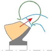
•Pre-Swirl [ for pumps, fans, compressors only ]
Here you may define the inflow swirl at hub and shroud. The following definitions are available:
|
Flow angle |
Swirl number |
Swirl energy number |
|
|
|
|
Positive swirl Negative swirl No swirl |
α < 90° α > 90° α = 90° |
δr < 1 δr > 1 δr = 1 |
δY > 0 δY < 0 δY = 0 |
Negative swirl is increasing the head and may often have no good affect to the suction behavior. Inflow through a straight pipe usually leads to swirl-free flow.
The different parameters can be converted:
![]()
![]()
![]()
The conversion δr - α is only valid for certain diameters dH and dS.
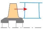
Except for radial-inflow turbines the general meridional shape of the machine, depending on the specific speed, is displayed in the right Values area:
|
|
|
centrifugal |
mixed-flow |
axial |
Furthermore some calculated variables are displayed:
Specific speed |
points to machine type and general shape of impeller |
Specific energy Y |
Pumps, Fans, Hydro Turbines: Compressors, Gas Turbines (perfect gas model): |
Power output PQ |
Pumps, Fans: |
Mass flow m |
Pumps, Fans, Hydro Turbines: Compressors: |
Total pressure difference Δpt |
Pumps, Fans: |
Compressor:
Volume flow (total) |
|
Inlet speed of sound (total) |
|
Inlet density (total) |
|
Outlet pressure (total) |
|
Outlet temperature (total, isentropic) |
|
Gas Turbine:
Volume flow (total) |
|
Inlet speed of sound (total) |
|
Inlet density (total) |
|
Outlet pressure (total) or static |
|
Outlet temperature (total, isentropic) or static, isentropic |
|
Hydro Turbine:
Net head |
|
The Cordier diagram contains relationship between specific speed and specific diameter.
See Cordier.
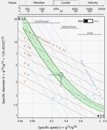
•In general for cost reasons single-stage and single-intake machines are preferred covering a range of about 10 < nq < 400.
•In exceptional cases it may become necessary to design an impeller for extremely low specific speed values (nq < 10). These impellers are characterized by large impeller diameters and low impeller widths. The ratio of free flow cross section area to wetted surfaces becomes unfavorable and is causing high frictional losses. To prevent this one may increase either rotational speed n or flow rate Q if possible. An alternative solution could be the design of a multi-stage machine reducing the energy transmission of the single-stage.
•If especially high specific speed values (nq > 400) do occur one can reduce rotational speed n or flow rate Q if feasible. Another option would be to operate several single-stage machines - having a lower nq - in parallel.
•Please note: CFturbo is preferably used between 10 < nq < 400 – centrifugal, mixed-flow and axial impellers.
Problem |
Possible solutions |
|---|---|
Energy transmission of all impellers is different to globally defined value. |
|
The sum of energy transmission defined for each impeller deviates from the globally defined value in Global setup. |
Check and adapt the energy transmission of the impellers (see Main dimensions) to get altogether 100% of the initially defined value of the Global setup. |
Total inlet pressure too small. |
|
Hydro turbines only: Head together with the inlet total pressure yields a discharge total pressure smaller then 0 with: . |
Increase total inlet pressure. |
Pressure and temperature not within the liquid phase of the fluid. |
|
If the fluid model = CoolProp, fluid properties will be calculated as function of pressure and temperature. In case pressure and temperature are above the vapor pressure curve, the fluid state is not valid. |
Increase inlet pressure, decrease inlet temperature. |