|
<< Click to Display Table of Contents >> Cordier |
  
|
|
<< Click to Display Table of Contents >> Cordier |
|
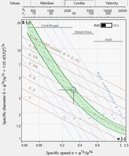
The Cordier diagram is based on an intensive empirical analysis of proved turbomachinery using extensive experimental data.
At the top right you can switch between different coordinate axes:
•relative: Specific diameter δ vs. Specific speed σ (or nq or Ns); original Cordier diagram
•absolute: Impeller/Rotor diameter d vs. Rotational speed n; valid for fixed design point values
Additionally, straight lines for the work coefficient ψ and the flow coefficient φ are displayed.
The Cordier diagram is displayed in Global setup and the Main dimensions.