|
<< Click to Display Table of Contents >> Multi stage |
  
|
|
<< Click to Display Table of Contents >> Multi stage |
|
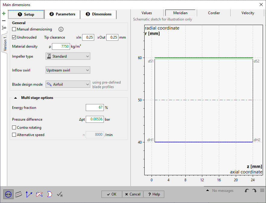
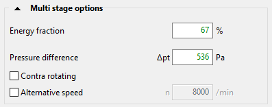
If more than 1 impeller or rotor shall be contained in the project this can be defined in the panel Multi stage options on page Setup.
[ Pump, Fan, Compressor ]
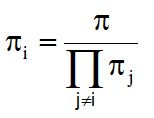
The design point (head, pressure difference etc.) can be distributed amongst the impellers using the power splitting. The energy goal used for the design of the selected impeller (index i) is determined by:
![]() ,
,
where the capital E may either be head, specific work or pressure difference resp. The lower case ei is the ratio describing the power splitting for the selected impeller. This ratio is to be defined by the track bar in the panel Multi stage options or can be directly specified underneath.
[ Gas turbine ]
In case more than 1 rotor is contained in the project the design point (Power output, pressure ratio) can be distributed amongst the rotors using the power splitting. The energy goal used for the design of the selected rotor (index i) is determined by:
![]() ,
,
where the P is the actual power output. The lower case ei is the ratio describing the power partitioning for the selected rotor. In case a pressure ratio π has been specified in the Global setup the pressure ratio used for the design of the selected rotor is determined by:
 .
.
The impeller may be defined with both a different rotating direction as well with a rotating speed different from the specifications set in the Global Setup. To this end the respective check box has to be set. If alternative speed is checked, an edit box appears in where the desired values has to be defined.
By activating the Automatic parameters and the Automatic main dimensions calculation, each change of the rotational speed results in an update of the main dimensions. This allows the rotational speed to be used to obtain a certain impeller diameter.