|
<< Click to Display Table of Contents >> Warning level |
  
|
|
<< Click to Display Table of Contents >> Warning level |
|
At Warning level one can specify recommended ranges and warning levels for some important impeller properties.
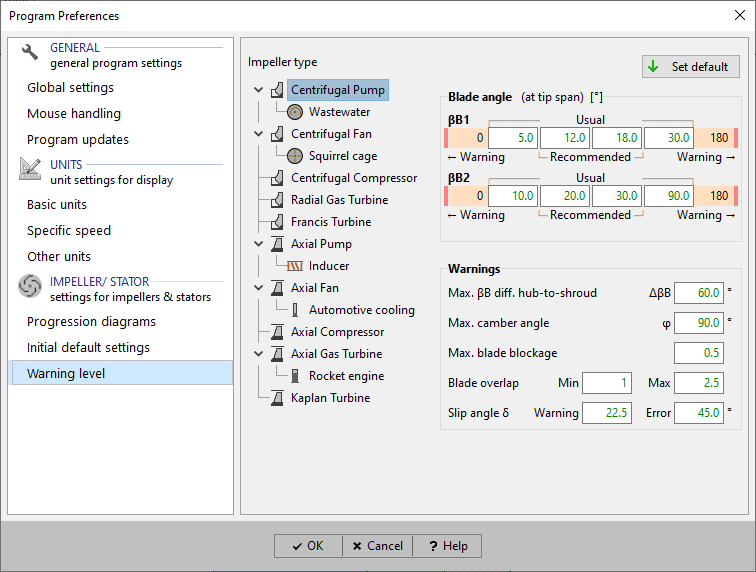
The usual and the recommended range can be specified. The displayed error levels cannot be customized.
Usually, the blade angle values at the outer blade tip/ shroud span of the blade are checked.
An exception is the outlet side of centrifugal impellers: due to the nearly constant radius the values at all spans are checked.
This max. allowed ΔβB along leading or trailing edge is used to avoid highly twisted blades.
This max. allowed value for φ = ΔβB = |βB2 - βB1| is used to avoid too high flow deflection on a single span.
The values are used to
•colorize the display of resulting blade angle βB2 in the main dimensions window of centrifugal impellers
•create warning messages in the Blade properties window/ design step
•colorize the blade angle values βB1 and βB2 in the
- Blade properties window
- Blade mean line window
- Blade profile (Airfoil) window
Blade thickness s is blocking a part of the flow passage u = πd/ number of blades. The blockage factor is calculated as F = s / u.
The max. allowed blade blockage factor can be defined.
The overlap factor is defined as F = wrap angle Δφ/ pitch angle t (t = 360°/ number of blades).
Min. and max. limits can be specified to avoid too low overlapping (poor flow guidance) and too high overlapping (high flow blockage).
Min. and max. limits can be specified to avoid unreasonable blade twist.
Warning and error level can be specified to avoid high deviation between blade and flow direction at trailing edge.