|
<< Click to Display Table of Contents >> Blade angles |
  
|
|
<< Click to Display Table of Contents >> Blade angles |
|
► Impeller | Blade properties ![]()
On this page the blade angles are calculated.
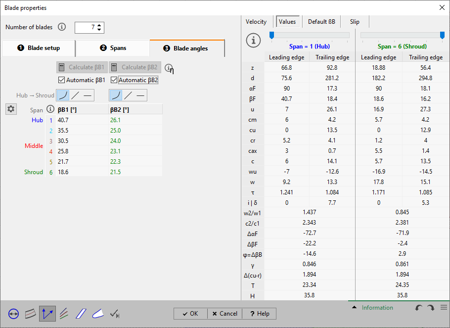
Later designed mean lines depend on the number and the meridional position of profile sections as well as the blade angles. Blade angles βB1 and βB2 are calculated from the velocity triangles, whereby the blade blockage of the flow channel and the slip velocity is considered.
The degree of freedom when designing the blades depends on the selected blade shape. Referring to the blade angles this means, that they are marked as (auto) and are result of the Mean line calculation.
The blade angles can be calculated on all spans. On panel Distribution from hub to shroud you can define how the blade angles of the inner sections are defined.
▪Calculation of blade angles using values from Blade setup by pressing button Calculate βB
▪Manual adaptation of calculated blade angles if required
Calculation or input of blade angles can be executed for each span (blade profile).
When using 2D blade shapes a low number of profiles may be sufficient in dependence of the leading edge shape, e.g. for a straight leading edge. For that reason the initial design for fans is made by 2 blade profiles.
Blade angles are computed under consideration of the equations listed below. They remain unchanged by default if they are determined once. If main dimensions or meridional contours are modified or, on the other hand, values of blade thickness or slip velocity are renewed, a recalculation of blade angles should be executed by pressing the button Calculate βB. This recalculation is made automatically if the checkbox Automatic is selected.
|
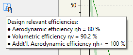
Efficiency values that are relevant for the blade angle calculation are displayed for information as hint. |
¢ Details of calculation of Inlet triangle
¢ Details of calculation of Outlet triangle
For special blade shapes some restrictions are existing and only the blade angles of the master mean line at hub can be calculated or adapted manually. The angles of all other sections are calculated automatically later during the mean line design because they depend on the mean line shape. This fact is indicated by the caption "(auto)" in the table. This means that there is a coupling condition based on the selected blade shape that results in an automatic calculation of the blade angles. The blade angles can be displayed in the mean line dialog in the “Informational values” panel.
For circular blades the radius of the blade R is displayed beside the blade angle table for information. This radius depends on the radii r1, r2 and blade angles βB1, βB2 at leading and trailing edge. If the calculation of the circular blade is not possible a warning symbol is displayed.
Problem |
Possible solutions |
|---|---|
Automated blade angles are active. |
|
Blade angles are updated automatically when input parameters are modified. |
To fix the blade angles you could uncheck the "Automatic" calculation. Then you have to manually start the calculation if required. |
Swirl gradient violates Euler equation. |
|
cu2*r2 is lower than cu1*r1 (turbines: cu2*r2 is higher than cu1*r1) resulting in energy transmission in the wrong direction (Euler equation of turbomachinery). |
Recalculate and/or check blade angles βB and flow angles β at leading and trailing edge. |
ΔβB1/2 (leading/trailing edge) = ... is larger than warning level of ... |
|
Blade angle difference (highest - lowest value) at all spans exceeds the warning level (see Preferences: Warning level). |
Check the resulting 3D blade shape and avoid high blade angle differences on spans if possible. |
ΔβB (span) = ... is larger than warning level of ... |
|
ΔβB = |βB2 - βB1| on one or more spans exceeds the warning level (see Preferences: Warning level). |
Check the resulting 3D blade shape and avoid high blade angle differences between leading and trailing edge if possible. |
Blade angles βB1/2 cannot be determined. Thermodynamic state could not be calculated. Check main dimensions, meridional shape or global setup. [ for compressors and turbines only ] |
|
The dimensions or meridional contour might be too tight for the specified mass flow and inlet conditions. |
Increase the dimensions (width etc.), meridional contour or change the Global setup (e.g. decrease mass flow). |