|
<< Click to Display Table of Contents >> Blade setup |
  
|
|
<< Click to Display Table of Contents >> Blade setup |
|
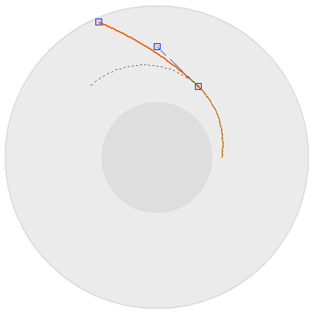
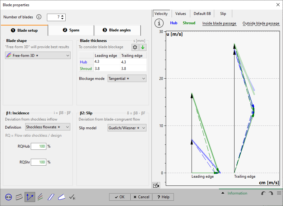
► Impeller | Blade properties ![]()
On page Blade setup basic blade properties are defined.
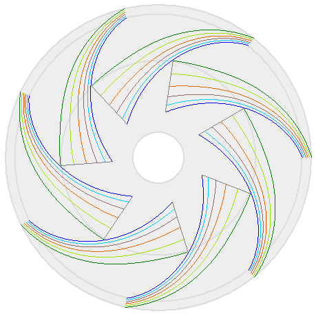
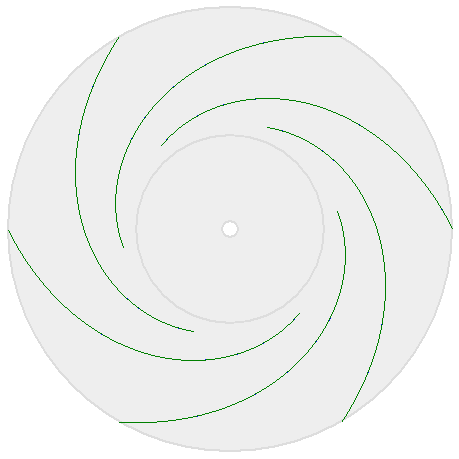
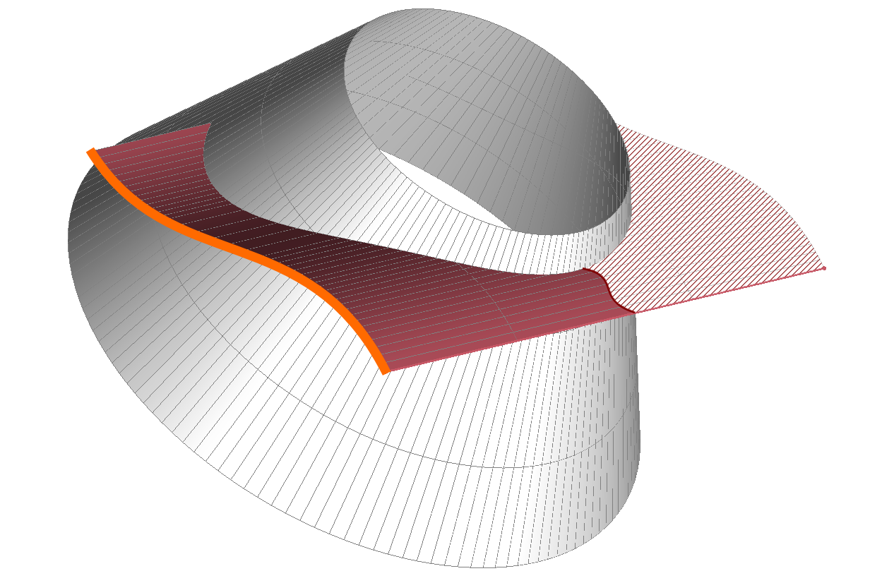
3D types: blade is curved in 3D
Free-form 3D |
|
|
|
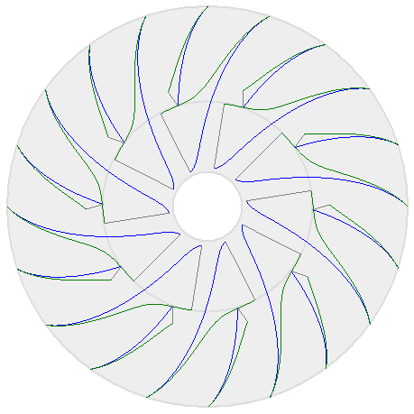
Helical 3D |
|
|
|
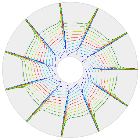
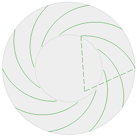
2D (axial) types: blade is curved in 2D when looking in axial direction
Free-form 2D (axial) |
Circular 2D (axial) |
|
|
Straight 2D (axial) |
|
|
|
|
|
|
|
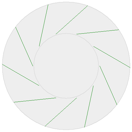
2D (radial) types: blade is curved in 2D when looking in radial direction
Free-form 2D (radial) |
Straight 2D (radial) |
|
|
The initial blade shape depends on the machine type and can be customized in the Impeller preferences.
PUMP |
|
Centrifugal & Mixed-flow |
Free-form 3D |
└ Wastewater |
Free-form 2D (axial) |
└ Barske (low nq) |
Straight 2D (axial) |
Axial |
Free-form 3D |
└ Inducer |
Helical 3D |
FAN |
|
Centrifugal & Mixed-flow |
Circular 2D (axial) |
└ Squirrel cage |
Circular 2D (axial) |
Axial |
Free-form 3D |
COMPRESSOR |
|
Centrifugal & Mixed-flow |
Ruled surface 3D |
Axial |
Free-form 3D |
TURBINE |
|
Radial & Mixed-flow |
|
Axial |
Free-form 3D |
Only the Free-form 3D blade shape provides complete flexibility, all other types result in limitations in blade angle specification and mean line design.
In case of Ruled surface 3D blade shape and linked splitter blades the linkage can be specified in more detail. See Ruled Surface blade.
|
Blade shape |
Impeller type |
Meridional shape |
Splitter blades |
3D |
Free-form 3D |
(no limitations) |
||
Ruled surface 3D |
||||
Radial elements 3D |
||||
Helical 3D |
axial impellers only |
|
not available |
|
2D (axial) |
Free-form 2D (axial) |
centrifugal & mixed-flow impellers only |
available only if the meridional direction is mainly radial: hub must overlap shroud in z-direction about 50% or more hub must not have axial parts within blade area |
|
Circular 2D (axial) |
||||
Straight 2D (axial) |
||||
Circular + |
not available |
|||
Logarithmic spiral + Straight 2D (axial) |
||||
2D (radial) |
Free-form 2D (radial) |
axial impellers only |
available only if the projection of the shroud mean line in radial direction (relating to leading edge point) hits the hub surface hub must not have radial parts within blade area |
not available |
Straight 2D (radial) |
||||
Blade thickness can be important for the blade angle calculation due to the blockage effect and flow acceleration.
By different thickness on hub and shroud side a tapering to the blade tip can be designed. Initial thickness values are based on empirical functions.
2 impeller types have special thickness requirements:
•Waste water pumps have very high thickness values at leading edge to avoid solid attachments (10% of d2 for 1 blade, 5% of d2 for more blades). The rest of the blade has smaller thickness of 30% relative to the max. thickness at leading edge.
•Inducer pumps have very low thickness values at leading edge to improve suction performance: 6%...10% of normal blade thickness.
Blockage mode
In general, it's a controversial issue to consider blade blockage effect for blade angle calculation or not and in which way. Exactly at blade edge the thickness is 0 due to the rounding of the blade edge. Immediately after the blade leading edge (or before the blade trailing edge) the blade is blocking the flow in a certain manner. This blockage is dependent on the blade thickness, the blade angle and the blade angle distribution and which is hence a rather complex with respect to the blade geometry. One can consider the blockage by the following modes:
•Tangential: the blade thickness is projected tangentially σ = s / sin(βB)
•Orthogonal: the blade thickness is not projected at all σ = s
•None: the blade thickness is not considered σ = 0
These options will have an influence on the calculation of the meridional velocity component cm and therefore on the blade angle calculation when pressing button Calculate βB or if the checkbox Automatic is selected. Beyond it, it will influence the meridional flow calculation too.
Pump, Fan, Compressor |
Turbine |
|
from ratio Q for shockless inflow / Q for max. efficiency |
RQ = QShockless / QBEP |
fully automatic by theory of WIESNER adapted by Aungier |
or directly by incidence angle i (RQ=100% or i=0° for shockless inflow) |
or directly by incidence angle i (i=0° for shockless inflow) |
|
or from ratio of incidence angle i / blade angle βB |
iRel = i / βB |
|
For inducer pumps there is an additional check if the incidence is > 1° even for high flow rates (overload) to prevent pressure side cavitation.
Squirrel cage fans have high incidence typically resulting in blade inlet angles β1B≈ 80°.
[ Pump, Fan, Compressor impellers only ]
You have to use one of the following slip models:
Slip model theory |
Hints |
closed empirical model, |
|
closed empirical model |
|
input of coefficient a |
|
User-defined |
manual selection of angular deviation ß2B-ß2 resp. velocity ratio cu2/cu2,∞ |
specific slip models for specific impeller types |
Using the button Show calculation details provides specific information about the βB2 calculation.
Problem |
Possible solutions |
|---|---|
Blade blockage factor of ... is larger than warning level of ... at leading/ trailing edge at hub/ shroud. |
|
Blade thickness s is blocking a significant part of the flow passage u = πd/ number of blades. The blockage factor is calculated as F = s / u. |
Reduce number of blades and/or blade thickness. |
Blade blockage factor of ... is outside the valid range of 0...1 at leading/ trailing edge at hub/ shroud. |
|
Blade thickness is blocking the flow passage completely at the specified position. |
Reduce number of blades and/or blade thickness. |
Blade number different than initially defined. |
|
Number of blades differs from the number that was initially selected in Main dimensions used for empirical correlations to calculate the main dimensions. This can result in inconsistent impeller design. |
It makes no sense to use other number of blades for main dimension calculation and blade design itself. Before modifying the number of blades here one should adapt the number in Main dimensions, update the empirical parameters and the main dimension. |
Mean lines (except hub) may be extrapolated. ("Free-form 2D" blade shape only) |
|
The hub is the master mean line for "Free-form 2D" blade shape. For this blade shape the geometry of all other mean lines is designed automatically in such way that it is exactly overlapping the hub mean line if viewing in z-direction. The resulting blade shape is two-dimensional. If the other curves have points with higher radius at trailing edge/ lower radius at leading edge than the last/ first hub point (sloping meridional edge), then these curves have to be extrapolated. |
Use axis parallel (const. radius) or slightly sloping meridional leading/ trailing edge. Leading edge: The shroud point should have higher or equal radius than the hub point. Trailing edge: The shroud point should have lower or equal radius than the hub point. |
Blade shape [Radial Elements 3D]: requires the maximum Z-extension |
|
The hub is the master mean line for "Radial elements 3D" blade shape. The geometry of all other mean lines is designed automatically in such way that it forms a blade consisting of radial fibers. The resulting blade shape is three-dimensional. If the other curves have points with lower z-values at leading edge/ higher z-value at trailing edge than the first/last hub point, these curves have to be extrapolated. In this case the blade would have a bad quality in the extrapolated region. |
Use radial (const. axial position) or sloping meridional leading/ trailing edge. Leading edge: The shroud leading edge should have a higher or equal axial position compared to the hub. Trailing edge: The shroud trailing edge should have a lower or equal axial position compared to the hub. |
"Ruled surface" blades may export low quality surfaces when using two mean lines only. |
|
Impeller with splitter blades can have wavy blade surface if only 2 blade profile sections are used. |
Increase the number of blade profile sections (page "Blade angles"). |
"Straight 2D (axial)" blades not possible for selected |
|
The hub mean line is the master mean line. All other mean lines are adapted automatically in order to overlap the hub mean line if viewing in z-direction. If the other mean lines are extended they will be extrapolated automatically. For specific combinations of meridional leading edge and blade angles βB1 an extrapolation is impossible. |
Leading edge: The point on shroud should be moved to a higher radius. βB1: Blade angle should be increased. |
"Circular + Free-form 2D (axial)" blades not possible for selected distance and angle combination. |
|
Construction of circular arc is not possible for given parameters. Therefor calculation of blade is blocked |
Modify αLE or aLE for this blade shape. For further information see Compound blade shapes. |
Extrapolation of "Circular + Free-form 2D (axial)" blades not possible for secondary spans. |
|
The minimal inner radius for the secondary spans is limited by the circular arc (design curve) defined by α3 and a3. |
Try to reduce effect of extrapolation by adjusting meridional Leading edge or change parameters defining the circular arc (design curve) of this blade shape. For further information see Compound blade shapes. |
"Straight 2D (axial)" blades not possible for selected |
|
The blade angle is too small or too large - therefore designing a "Straight 2D" blade shape is impossible.
|
Trailing edge: The edge should be moved to a higher radius. αLE/βLE: Blade angle should be increased. |
"Straight 2D (radial)" blades not possible for selected Blade angles not within a valid range. |
|
Projection of the designed mean line onto the other spans fails for this blade shape.
|
Blade angle should be specified within the recommended range. |