|
<< Click to Display Table of Contents >> Blade mean lines |
  
|
|
<< Click to Display Table of Contents >> Blade mean lines |
|
► IMPELLER | Blade mean lines ![]()
The blade mean lines are designed on the number of meridional flow surfaces which were determined in Blade properties.
Depending on the selected blade shape (see Blade properties) the design of the mean lines is more or less restricted.
The blades of an impeller representing a deceleration cascade for the relative velocity. Therefore the risk of flow separation exists. The user should try to obtain a continuous, smooth change of flow direction, as well as the cross section graduation of the flow channel should be as steady as possible.
The splitter blades are displayed and designed on a separate tab (Splitter blade).
The design options depend on the link between main and splitter blades in the Blade properties. If Splitter blade linked to Main blade is activated there, the splitter blade is a shortened main blade. The blade and wrap angles are calculated automatically.
The relative position of the splitter blade between two main blades can be adjusted. In case of linked splitter a single value can be specified only, for unlinked splitter the full flexibility is available.
Some more blade information is displayed in tables and diagrams in order to check the design and for informational purposes:
¢ See Additional Views
Select the currently available mode to design the blade mean lines.
¢ See Design mode
For continuous transition between the separate mean lines (blade surface), the matching points of each mean line have to be Coupled linear. If you deactivate this option then you can modify all mean lines independently.
If the linear coupling mode is active you can move and rotate the connecting line. The positions of Bezier points of all mean lines are modified correspondingly, to get uniform profiles. If you select a point of the inner cross sections you can move the entire connecting line.
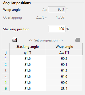
The current average wrap angle of all mean lines is displayed. When design mode = conformal mapping, this value can be modified or reset to default value resulting in the same value for all mean lines, based on empirical functions. The wrap angle of each mean line is given in the table.
The stacking position is the relative position at which the mean line is stacked. It can be set only for blades having more than 1 active mean line, e.g. Freeform 3D or Ruled surface 3D. In case of design mode = conformal mapping, the stacking position is zero and cannot be altered currently.
The location of the stacking curve at which the stacking position is applied is determined by the φ-position given in the table. It therefore determines - together with the stacking position - the location of the Leading edge / Trailing edge. For some blade shapes, user defined values can be specified, either directly in the table or using a progression dialog (buttons above the columns).
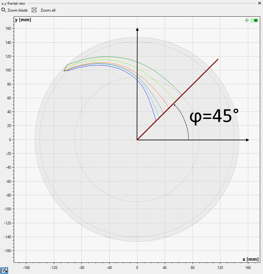
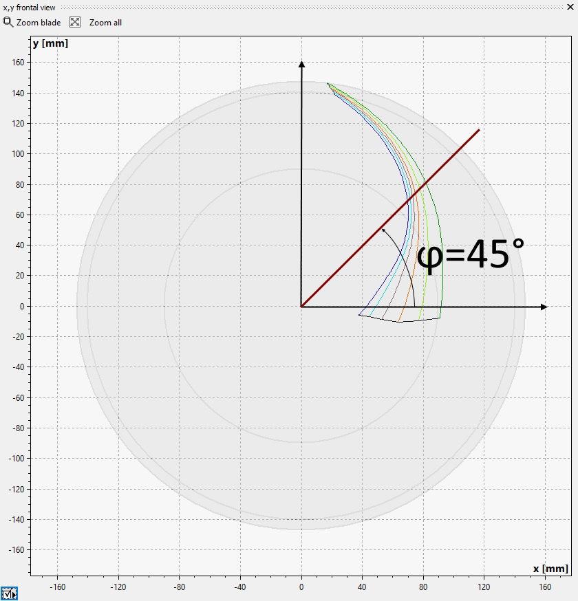
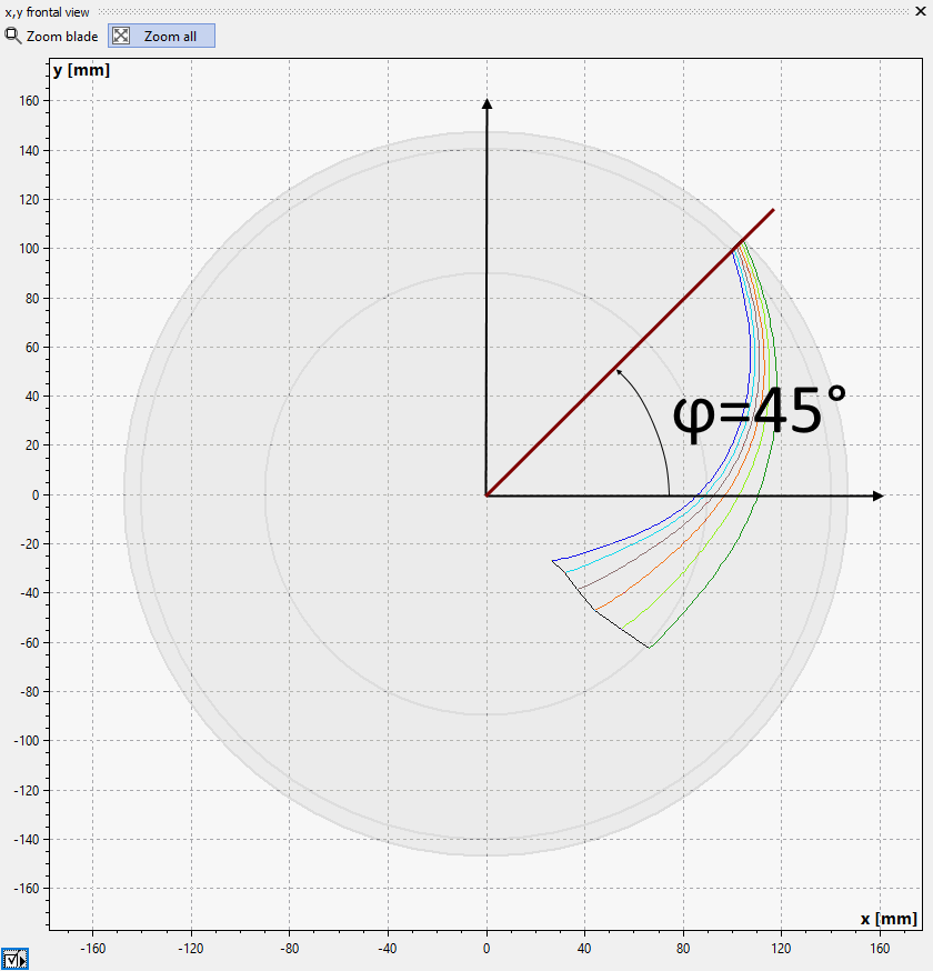
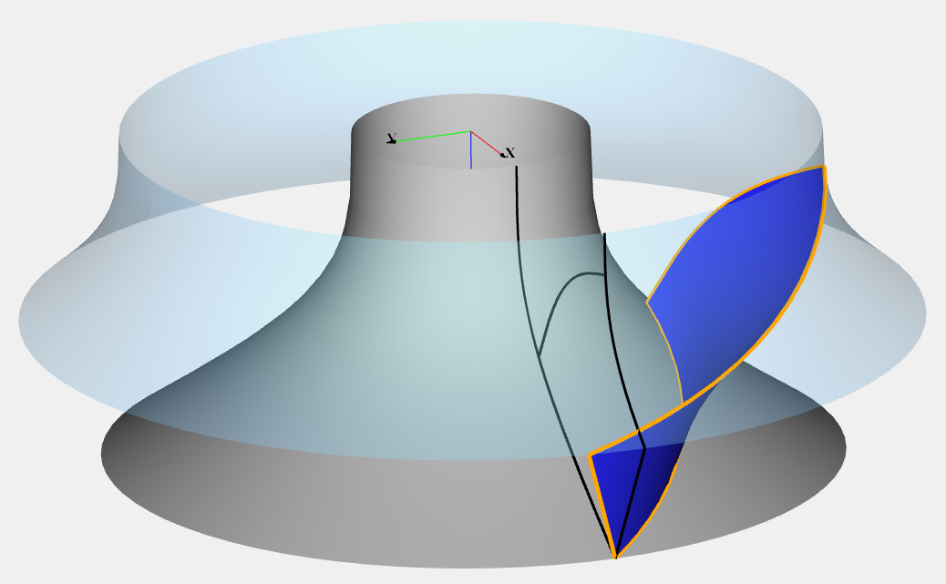
Shown below are examples with a straight stacking curve located at a stacking angle of 45°. If the stacking angle is different on each span, the stacking curve is not linear. The mean lines are stacked at this curve at the given stacking position:
0% = leading edge |
50% = mid |
100% = trailing edge |
|
|
|
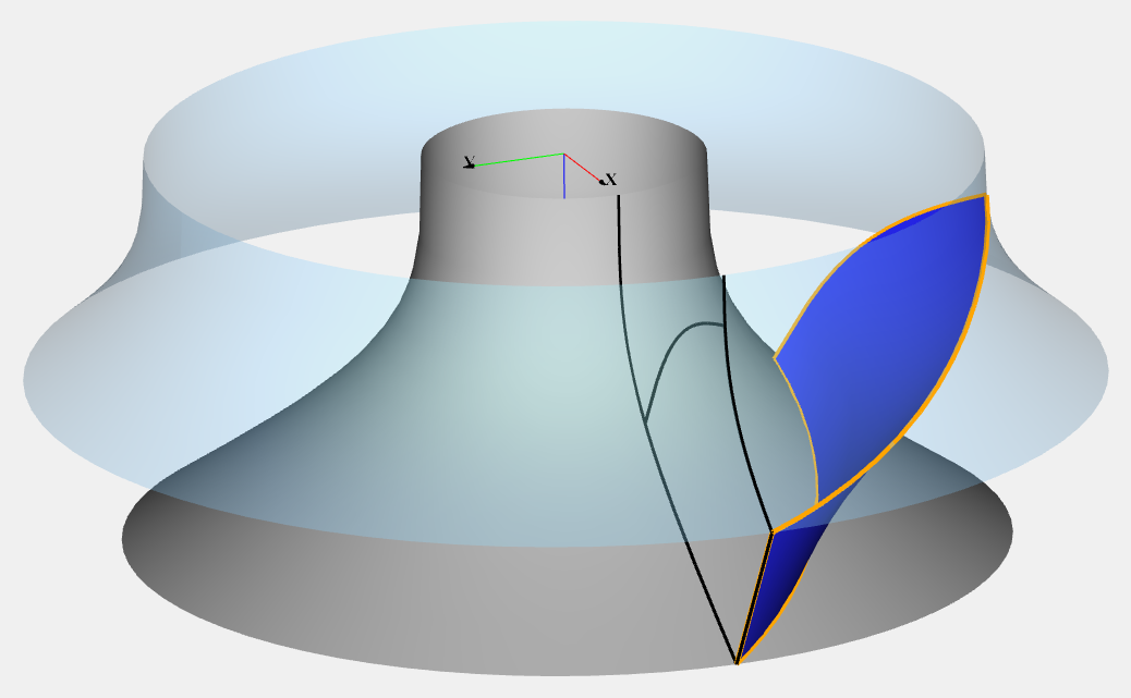
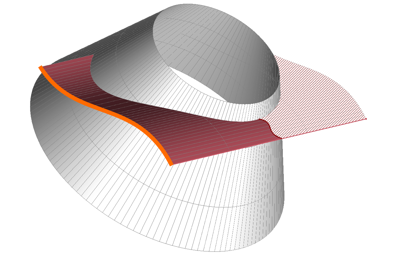
The rake angle α is the angle between the meridional plane and the leading or trailing edge respectively. The following pictures depict a blade with zero rake angle (left) and α = -20° (right).
Blade with rake angle α = 0° |
Blade with rake angle α = -20° |
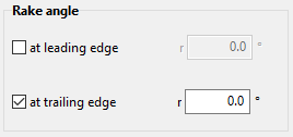
The rake is determined by (see picture below):
![]()
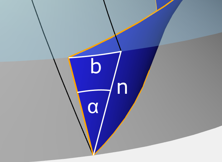
The rake angle can be set directly when the blade shape is either Free-form 3D or Ruled Surface 3D. In case of Design mode = conformal mapping rake angles at leading and trailing edge can be set both. For different design modes only one rake angle can be set. The other one is determined by the geometric restrictions.
Problem |
Possible solutions |
|---|---|
Blade angles and blade extensions could lead to unusual blade shapes. |
|
Blade angles and blade extensions could lead to non-feasible blade shapes. |
|
The values of the blade angles βB1, βB2 and the meridional and tangential blade extension most likely result in an abnormal or strange blade shape. To avoid any subsequent problems such mean line shapes are blocked. |
In theses cases the blade is highly curved or has a S-shape. To design a reasonable blade the wrap angle has to be not too low and not too high. You can |
ΔβB1/2 (leading/trailing edge) is higher than warning level |
|
Blade angle difference (highest - lowest value) at all spans exceeds the warning level. The resulting blade could be highly twisted. |
Check the resulting blade shape and avoid high blade angle differences on spans if possible. |
ΔβB1/2 (leading/trailing edge) is higher than error level |
|
Blade angle difference (highest - lowest value) at all spans exceeds the error level. Blade design based on these extreme values makes no sense. |
Decrease the blade angle differences on spans. |
Blade calculation failed due to boundary conditions and constraints. |
|
Projection of the design mean line onto the other spans fails for this blade shape.
|
Decrease wrap angle. |
Very high tangential leading edge sweep angle. |
|
Leading edge sweep angle (tangential difference between hub and shroud meanline at LE) is very high. This curved shape could result in abnormal or strange blade shape. |
Adapt blade properties, e.g. blade angles. In some situations, it might be helpful to increase the number of spans if possible. |
Too high tangential leading edge sweep angle. |
|
Leading edge sweep angle (tangential difference between hub and shroud meanline at LE) is too high. A reasonable blade cannot be generated. |
Adapt blade properties, e.g. blade angles. |
Blade edge exceeds the meridional boundaries. |
|
The meanlines of inner blade spans are crossing the meridional extents at leading or trailing edge. This is only possible for ruled surface blades with more than 2 spans. |
Change meridional position of leading/ trailing edge or reduce number of spans to 2. |
Meridional extension mTE is different compared to meridional design. |
|
Current meridional coordinates (m) of trailing edge deviate from the extension specified in the meridional contour design step. This is possible for imported geometry only (polylines). |
Adapt imported m,t-curves to match the meridional extension. It is more comfortable to switch the mean line curve mode from "Polyline" to "Bezier curve" before modifications are made in previous design steps. |
Blade angles βB1 and/or βB2 are different compared to blade properties. |
|
Current blade angle values deviate from the specified values in Blade properties. This is possible for imported geometry only (polylines). |
Check imported m,t-curves or β-curves and compare with specified β values at leading and trailing edge. The values resulting from the current meanlines are displayed in "Additional views/ Informational values/ Blade angle βB". |
Overlapping of adjacent blades might be too low/ high. |
|
Unusual blade overlapping, which is defined by the overlapping factor F = Wrap angle Δφ/ Pitch angle t (t = 360°/ number of blades) The min./ max. warning level is defined in Preferences: Warning level. |
Modify the blade wrap angle Δφ and/ or the number of blades (see Blade angles). |
Coupling partially deactivated. |
|
The mean lines are currently not linearly coupled, which can result in deformed blade surfaces. Either linear coupling has been deactivated or it is impossible because of highly deviating blade angle values. The warning occurs because the intersection of βB2 line and intersection line for one or more mean lines cannot be determined. Usually this has one of the following causes: a)It is geometrically impossible to determine this intersection (approximate parallel lines). b)The intersection is not between the points of hub and shroud mean line. c)The point of intersection is too close to the endpoints of the mean line (lower than 5%). |
Activate linear coupling if it is deactivated. Homogenize βB2 blade angle values (see Blade properties). |
Curvature very high. Swirl change might not be as high as intended. |
|
One or more mean lines do not change their direction smoothly enough in the m,t coordinate system resulting in partially high curvature (βB gradient). The flow does not follow this high curvature and thus the swirl change is much lower as intended. In addition, the blade profile design cannot follow the hook-shaped mean lines. |
Design the mean line progression from leading to trailing edge more smoothly by modification of the inner control points and the wrap angle. In particular, the blade angle progression should be checked. Very high difference between βB1 and βB2 can make the solution of the problem more difficult and could require a higher wrap angle. |