|
<< Click to Display Table of Contents >> Blade profile |
  
|
|
<< Click to Display Table of Contents >> Blade profile |
|
► IMPELLER | Blade profiles ![]()
To create 3D blade profiles the specified or calculated values from the Blade properties are used:
•Profile shape based on profile selection
•Chord length (scaling) and Stagger angle (rotation) of each profile at the respective span position based on profile properties
The resulting 2D profiles are displayed top left in the dialog whereas the thickness distribution at each span location can be found below.
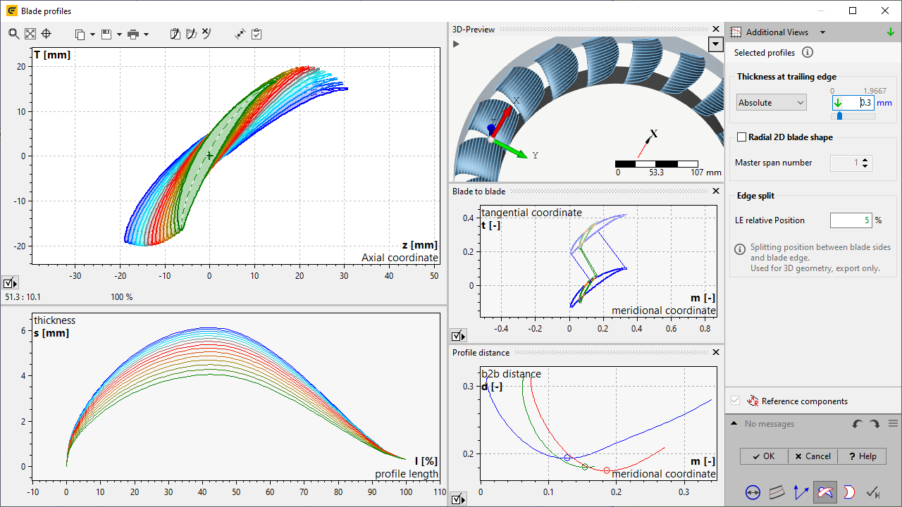
The following information can be displayed using the "Additional views" button:
•Informational values: resulting blade angles at leading (βB1) and trailing edge (βB2).
•3D-Preview: 3D blade shape after the 2D blade profiles were projected into its span surface as well as surfaces of hub and shroud and mean surfaces.
|
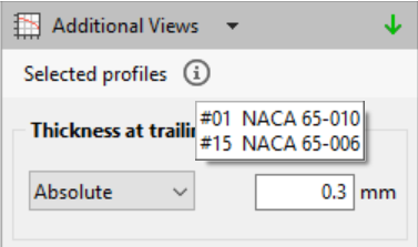
The previously selected blade profile names are displayed for information as hint. For NACA 4 Digit, NACA 65 series and Point-based profiles the trailing edge thickness can be adapted for manufacturing reasons. The additional thickness is added linearly over the length of the profile. |
Two modi are available. The thickness value is applied for those spans at which NACA profiles are specified (not interpolated), see blade properties. |
|
Relative |
Absolute |
||
Thickness is chord length times relative thickness |
Thickness is equal the absolute thickness |
||
Radial 2D blades can be designed by using a constant stagger angle of a selected master span profile.
Please note: By applying the radial 2D blade shape the aerodynamic properties of the resulting blade will be different from those stated in the Blade properties.
The edge split position defines the transition from blade suction/ pressure side to the leading edge. It's used for the 3D model generation as well as for the data export.