|
<< Click to Display Table of Contents >> Blade sweep |
  
|
|
<< Click to Display Table of Contents >> Blade sweep |
|
► IMPELLER | Blade sweep ![]()
In this design step the blade sweep can be optionally specified. Blade sweep is normally only useful for acoustic reasons and comes at the cost of slightly reduced efficiency.
In default configuration this design step does not generate any sweep by aligning the centroid points of all profiles exactly in radial direction. You can return to an unswept configuration at any time by using the Reset sweep curve option.
The left area of the dialog is comprised of four diagrams that display the current blade sweep definition, represented in several projections. Depending on the Sweep mode (see below) selected, only two of these diagrams are active at a time, whereas the other two diagrams are merely informative.
The design curves (orange) in active diagrams exhibit control points which are movable along design guide lines (gray) which subdivide the radial space between Hub (blue) and Shroud (green).
The user designed sweep projections are combined into the 3D sweep curve which is then applied to the blade geometry by stacking the blade profiles along it. The informative sweep projections are updated accordingly.
Independently of Sweep mode the blade positioning in the meridional contour can be controlled in the axial projection diagram (top left). Blade positioning can be controlled via a special control point at the base of the sweep curve, which can be moved along the Hub contour and that moves the blade geometry along with it. Design configurations where the Blade exceeds the meridional boundary have to be corrected by adjusting the blade position in order to finish this design step successfully.
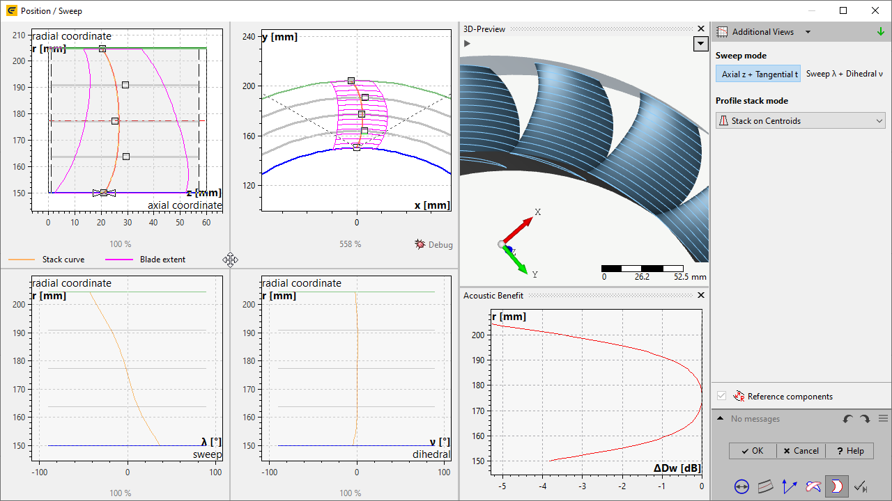
The following information can be displayed using the "Additional views" button:
•Informational values: Any sweeping will yield a certain deterioration of the aerodynamic performance compared with the unswept state. The sweep correction μ is a quantitative expression of this and is based on an empirical co-relation. To compensate for the sweeping losses the sweep correction will be applied when profile properties are newly calculated.
•3D-Preview: The final result of the sweep design process, the swept 3D blade shape as well as surfaces of hub and shroud and mean surfaces
•Acoustic benefit: ...compared to the unswept blade design
![]()
The Sweep mode controls which of the 2D Sweep projections define the blade sweep and are modifiable by the user.
For defining a blade sweep two alternative options are available:
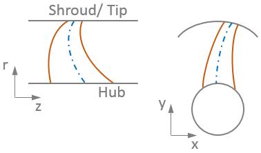
•Axial z + Tangential t
Sweep projected in meridional and axis-normal view.
This view also shows the blade outline.
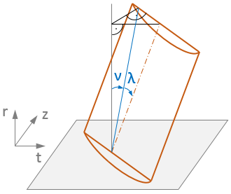
•Sweep λ + Dihedral ν (default)
λ: Incidence not perpendicular to blade axis, blade area nevertheless in flow direction
ν: Blade plane not perpendicular on hub, defines V-positioning
The profile stack mode controls how 2D-Profiles are stacked relative to profile geometry onto the 3D-sweep curve. This Design choice will subsequently also be reflected in the display of profiles in the previous Blade profile dialog.
The blade sweep for each sweep mode can be defined on one of the following blade profile positions:
•![]() leading edge
leading edge
•![]() centroids (default)
centroids (default)
•![]() trailing edge
trailing edge
Problem |
Possible solutions |
|---|---|
The air/hydrofoil blade is not located within the predefined blade area. Either extend the meridional blade area or reposition the blade. |
|
The axially projected chord length is higher than the meridional length or the predefined blade area. |
Increase the meridional extension or/and the predefined blade area (meridional contour) or adjust chord length and stagger angle (blade properties) or change the blade position. |