|
<< Click to Display Table of Contents >> Dimensions |
  
|
|
<< Click to Display Table of Contents >> Dimensions |
|
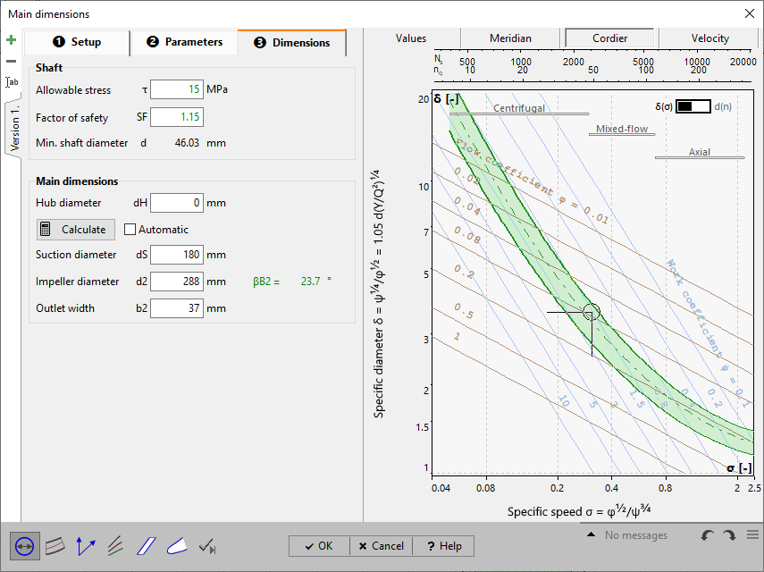
In the panel Shaft, the required shaft diameter is computed.
¢ Shaft/ Hub
The hub diameter is determined by the user and depends on the shaft-hub connection.
The main dimensions can be seen on Main dimensions panel. They can be recomputed by pressing the Calculate-button. The computation is based on "Euler's Equation of Turbomachinery", on the continuity equation and the relations for the velocity triangles as well as on the parameters given in the tab sheets Setup and Parameters.
Individual main dimensions can be calculated separately using the button inside the value field.
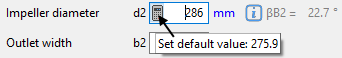
You may accept the proposed values or you can modify them slightly, e.g. to meet a certain normalized diameter.
In case the checkbox Automatic is activated a new calculation will accomplished after any change of parameter. Then the manual alteration of the main dimensions is not possible.
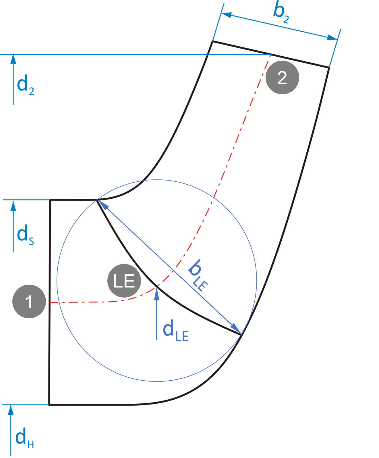
Due to the Euler equation the impeller diameter d2 and the blade angles βB2 are coupled (see Outlet triangle). Lower d2 values result in higher βB2 (higher blade loading) and vice versa. For that reason the resulting average βB2 value is displayed for information right beside the calculated/ specified d2 value.
![]()
|
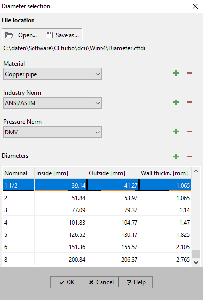
You can select a value for the diameters dS from standard specifications. For that purpose you have to press the settings button The small dialog gives you the possibility to select a diameter from several standard specifications. If material, standard name and pressure range are selected the lower panel shows all diameters of the chosen standard. One diameter is highlighted as a proposal. Nominal diameter, outside diameter and wall thickness for the marked entry is displayed. Using of At File location the name of the file containing the diameters is shown. The file is originally called Diameter.cftdi and is located in the installation directory of CFturbo. Modifications of the list will be saved if the user is leaving the dialog window by clicking the OK-button. In case there are no write permissions the user can choose another directory to save the file. Renaming of files is possible by Save as- functionality. By clicking the Open-button a previously saved file can be opened. |
Neighboring components
In specific cases the dimensions of the neighboring components at inlet and/ or outlet can be used to get exactly matching geometry.
![]()
This feature is available only for explicitly uncoupled components or side-by-side impellers.
In the right panel of any tab sheet an information panel is situated, which holds the computed variables in accordance to the actual state of design, the resulting Meridional section as well as the Cordier-Diagramm with the location of the best point. These three sections can be chosen by the appropriate soft buttons in the heading.
In the Value section the following variables are displayed for information which result from calculated or determined main dimensions:
Flow properties at: |
static pressure p |
Velocity triangles at: |
velocities u, cm, cm*, cu, c, wu, w |
Work coefficient |
|
Flow coefficient |
|
Meridional flow coefficient |
|
Specific diameter |
|
Inlet velocity |
|
Inlet velocity (net) |
|
Outlet velocity |
|
Outlet velocity (net) |
|
Outlet width ratio |
|
Meridional deceleration |
|
Estimated axial force |
|
Reynolds number |
with d1 = highest diameter at inlet |
with b1 = width at inlet |
|
with d2 = highest diameter at outlet |
|
with b2 = width at outlet |
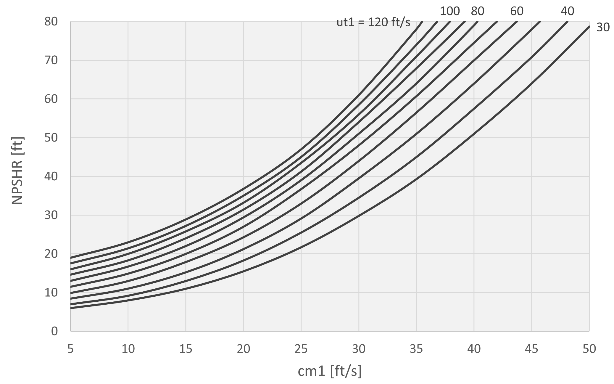
NPSHR estimation |
(Available at inlet)
Available head level distance to vaporization at impeller inlet (pv = fluid vapor pressure) |
Lobanoff/ Ross
see diagram below this table |
|
Pfleiderer
|
|
Gülich
|
|
Stepanoff
|
|
Petermann
|
|
Europump
|
|
NPSHR prediction |
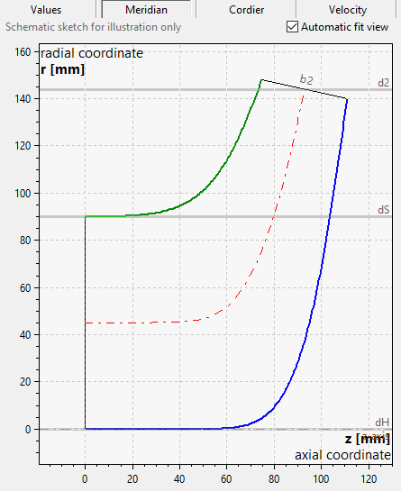
The Meridional preview is until now based on the main dimensions only.
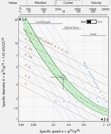
The Cordier diagram can be used for checking the impeller diameter d2.
See Cordier.
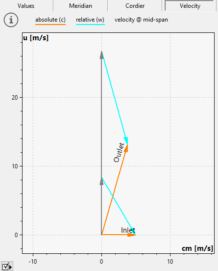
The Velocity triangles are the result of a mid-span calculation and are based on the design point and the main dimensions.
Problem |
Possible solutions |
|---|---|
Use of dS/d2 requires dH=0. |
|
This applies for fans only. If the suction diameter dS is calculated by diameter ratio dS/d2, then the hub has to be planar, i.e. hub diameter dH = 0. Otherwise the empirical correlations are invalid. |
Select a different parameter for the calculation of the suction diameter dS (see Parameters). |
Inlet/ Outlet: Pressure and temperature not within the liquid phase of the fluid. |
|
|---|---|
If the fluid model = CoolProp, fluid properties will be calculated as function of pressure and temperature. In case the local pressure and temperature are not above the vapor pressure curve, the fluid state is not valid. |
Increase main dimensions (width, diameter etc.) or change Global setup (e.g., decrease mass flow, increase pressure, decrease temperature). |