|
<< Click to Display Table of Contents >> Euler based |
  
|
|
<< Click to Display Table of Contents >> Euler based |
  
|
The Euler-based performance prediction is available for all types of turbomachines.

There are different kinds of losses that are considered in different curves:
Kind |
Description |
Parameter |
|
Decreased power |
Based on the Euler-Equation and the decreased power that is calculated in the Blade properties. In the design point the decreased power line is shifted by a pressure head loss equivalent to the decreased power (HDecr=Hth-ΔHDecr). The decreased power line can be parallel to the Euler-Line as well as positioned that way, that it intersects the Euler-Line at Δp = 0. |
cl: cl = 1...parallel position, cl = 0...intersection with Euler-Line at Δp = 0. |
|
Hydraulic losses |
Based on the Euler-Line including the decreased power minus the losses due to friction. Yields a downwards opened parabola, that touches the decreased power curve at Q = 0. |
ζh: General approach:
|
F: Flow factor that considers the geometry of the component (inlet and outlet area)
|
Shock losses (by turbulence and separation) |
Includes all the effects listed above plus turbulence and separation losses at the inlet and outlet. Yields a downwards opened parabola. It touches the curve, in which decreased power and hydraulic losses are considered, in the point of shockless flow Qopt. Here the flow direction is tangential towards the leading edge. |
ζs: General approach:
|
|
The display of resulting performance curves can be toggled by the check box "All performance curves" (![]() display options lower corner in the left). In case the curves are to be hidden only the actual performance curve (red color) considering all losses will be visible.
display options lower corner in the left). In case the curves are to be hidden only the actual performance curve (red color) considering all losses will be visible.
A loss coefficient, that describes the hydraulic losses, can be calculated by pressing "Calculate ζ" in a way, that as a result the actual performance curve (red) of the flow efficiency will go through the best point. For this calculation the ratio between the loss coefficients is important. This ratio ζh/ζs can be set in the panel Parameter, see table below, second column.
Energy and flow rate variables plus flow rate limits (for turbines additionally a max pressure ratio) |
Coefficients influencing the decreased power (cl) and the hydraulic as well as shock losses (ζh, ζs) |
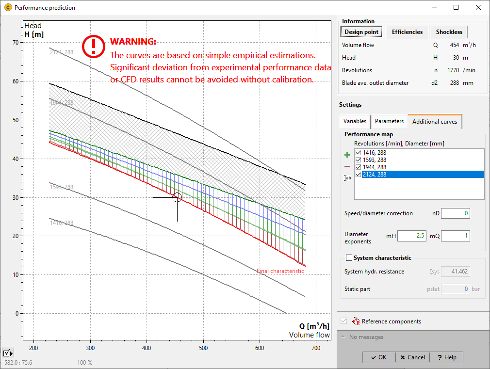
Additional curves with different speeds and diameter plus system characteristic |
|
|
|
The two quadratic approaches towards the description of the hydraulic as well as shock losses (i.e. turbulent and separation losses) tend to generate characteristics that have their efficiency maximum at flow values smaller than the design flow. To overcome or mitigate this certain parameters can be adjusted.
The general approach for the hydraulic losses is extended by an extra offset that is caused by a blind flow QBlind due to recirculation at a flow of Q = 0. This blind flow QBlind is determined with:
![]() .
.
Herewith the hydraulic losses become:
![]() ,
,
where weight can be influenced by the weight factor ζw in the panel Parameter, see table above, second column.
To influence the determination of shock losses at Q < Qopt a second weight factor cw is available. With the help of this parameter the shock losses become:
![]() .
.
The prediction of surge line is based on the following model: The pressure difference between outlet and inlet yields a back flow within the compressor. Amongst pressure difference and back flow a correlation exits, that can be found in the table "Kinds of losses", column "Hydraulic losses". Within the applied model the compressor is thought as a parallel connection between a flow source and a hydraulic resistance. Then, surge will occur when the back flow in the hydraulic resistance becomes as big as the flow in the flow source.
The surge line can be controlled by the loss coefficient "Surge loss coefficient". Of course it is impossible to consider non-steady effects that are characteristic for the onset of the surge with this model. The surge line can be displayed only in case dimensional variables has been chosen and the checkbox "Surge line" has been set (![]() display options lower corner in the left).
display options lower corner in the left).
With centrifugal fans surge may only happen if the pressure difference is big enough (~0.3 bar).
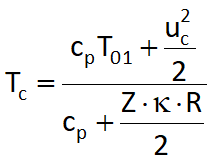
Choked flow will happen if the flow reaches sonic speed somewhere in a duct. As the rothalpy is constant at any point in the flow channel the temperature (critical temperature within the narrowest cross section) at a flow at sonic speed can be calculated by:

and critical sonic speed becomes:
![]()
With an approximation of the critical density and the influence of the boundary layer blockage the choked mass flow is:
![]()
The blockage of the boundary layer is expressed by the factor B that is 0.02 by default. This theoretical choke line can be displayed when the checkbox "Consider choke" has been set (![]() display options lower corner in the left).
display options lower corner in the left).
With the current set of parameters performance curves with different rotational speeds can be calculated and displayed. This procedure is feasible only if the rotational speeds are not too far from the design point. If they are, similarity relations are not valid any longer.
Running a turbomachines with a speed different from the design point the resulting efficiency will be smaller as the design point efficiency. To take this into account losses are scaled with the help of a Speed/diameter correction factor nD, see table Settings, last column. The resulting losses will be:
 .
.
Performance curves for impellers with decreased diameter can be calculated and displayed too. The decrease of the impellers means that the geometric similarity is not given anymore. Therefore performance curves are calculated by the following empirical correlations: H' = H (d'/d)mH and Q' = Q (d'/d)mQ. The exponent mH should be within 2..3, mQ should be 1 or slightly bigger.
Similar to the correction of characteristics with different speeds those with different diameters will be corrected with:
 .
.
An operating point, in which a turbo machine could possibly run, can be determined by a fictive system characteristic. The display of a system characteristic can be controlled by the checkbox "System Characteristic". The system characteristic consists of a static and a dynamic part. The static part is dependent on the parameter "Geodetic Head" (pumps only) and "Static part" respectively, whereas the dynamic part is dependent on the parameter "System hydraulic resistance". The system characteristic can only be displayed if head or total pressure difference have been chosen as variable.