|
<< Click to Display Table of Contents >> Blade mean lines |
  
|
|
<< Click to Display Table of Contents >> Blade mean lines |
|
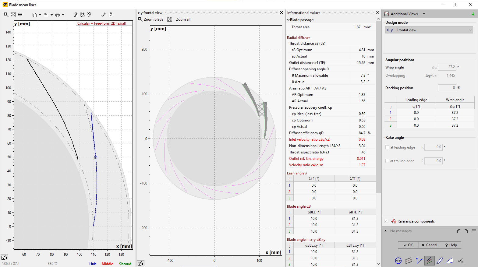
► STATOR | Blade mean lines ![]()
In principle, the same features are available as for the mean lines of impellers.
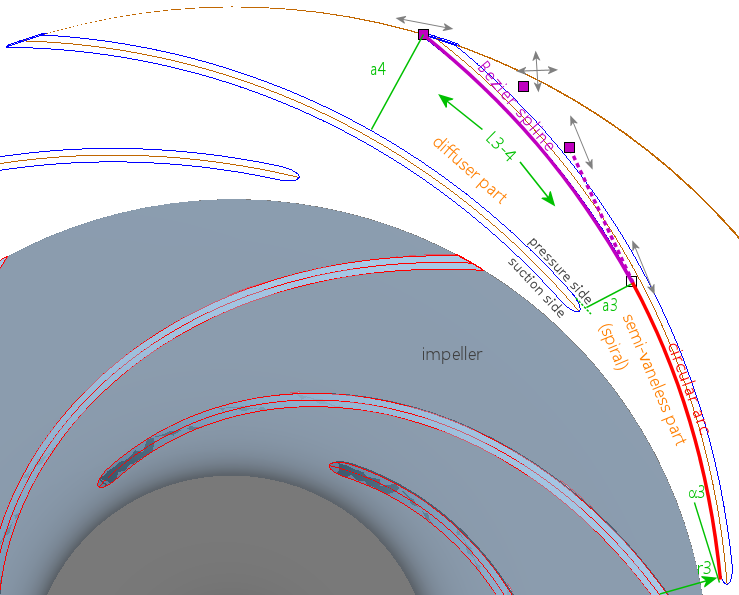
For special radial diffuser blade shapes "Log. Spiral + Straight 2D" and "Circular + Free-form 2D" the mean line design is made in the frontal view. The mean lines are the inner vane sides (concave sides).
Initially the blade thickness is ignored for the mean line design (red/magenta in the sketch). The opposite side if the flow channel is generated by rotation and adding the blade thickness. The blade thickness is assumed as linear between sLE and sTE (see blade properties), if the thickness distribution was not defined yet. Otherwise the thickness distribution defined in the blade profile design is used. In the later blade profile design the thickness is added to one side of the mean line only.
Diffuser area has to be designed carefully in order to minimize losses. The quality of the diffuser design can be verified according to the following criteria (see panel Radial diffuser in Informational values area). Values outside the recommended range are displayed in red color.
Name |
Description |
Definition/ recommended range |
Throat distance a3 (LE) |
Throat width at inlet (leading edge) |
|
a3 Optimum * |
Optimal value: average of calculation by const. swirl and deceleration ratio |
see blade properties |
a3 Actual |
Actual value: shortest distance from vane leading edge to neighboring vane |
|
Outlet distance a4 |
Shortest distance from vane trailing edge to neighboring vane |
|
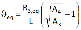
Diffuser opening angle θ |
Allowable diffusion angle |
|
θ Maximum allowable |
Max. allowable value to avoid flow separation depending on equivalent inlet radius and length |
|
θ Actual |
Actual value calculated by equivalent inlet radius, length, inlet and outlet area |
|
Area ratio AR=A4/A3 |
Area or deceleration ratio |
|
AR Optimum * |
Optimal value |
|
AR Actual |
Actual value |
AR < 3 |
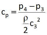
Pressure recovery coeff. cp |
Pressure recovery of the diffuser identified by a dimensionless coefficient |
|
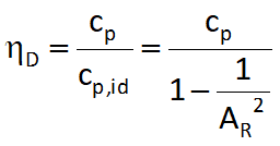
cp Ideal (loss-free) * |
Pressure recovery in an ideal (loss-free) diffuser |
|
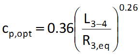
cp Optimum * |
Pressure recovery for optimal area ratio AR |
|
cp Actual * |
Pressure recovery in real diffuser (with energy losses) |
based on test results; plotted in diagrams; target: cp,act = cp,opt |
Diffuser efficiency ηD * |
Diffuser efficiency |
|
Inlet velocity ratio c3q/c2 |
Inlet deceleration ratio |
c3q/c2 = 0.7...0.85 for low specific speed |
Non-dimensional length L34/a3 |
Ratio of length to throat width |
L3-4/a3 = 2.5...6 |
Throat aspect ratio b3/a3 |
Ratio of inlet width to throat width |
b3/a3 = 0.8...2 |
Outlet rel. kin. energy * |
Kinetic energy of diffuser outlet; to minimize losses in the overflow channels of multistage machines |
|
Velocity ratio c4/c1m * |
Ratio of outlet velocity to inlet velocity of downstream impeller of multistage machines |
c4/cm1 = 0.85...1.25 |
* for radial diffusers of pumps only