|
<< Click to Display Table of Contents >> Cut-water |
  
|
|
<< Click to Display Table of Contents >> Cut-water |
|
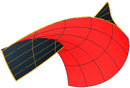
► VOLUTE | Cut-water ![]()
The geometry of the cut-water can be designed in this dialog box.
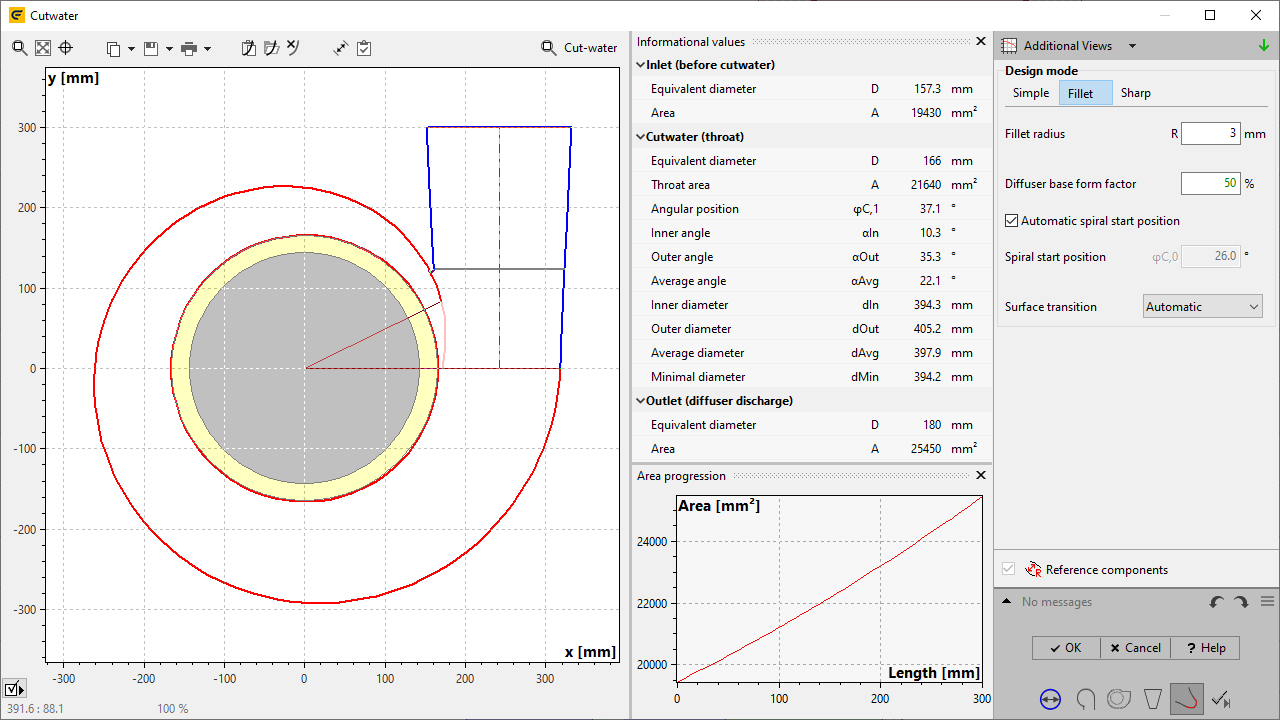
Generally, the cut-water can be designed in three modes: Simple, Fillet or Sharp.
The leading/trailing edge axis ratio specifies the ratio between the minor and major axis length of an ellipse, representing the leading and trailing edge of the splitter.
General |
The wrap angle must be at least 330°. |
Simple |
For cornered spiral cross sections the side position is fixed to the corner position and cannot be modified individually. |
Rounding of cut-water edges (Round edges) is possible only if side position is higher than the position of maximum curvature and if no diffuser radial offset is defined. |
|
Fillet, |
Not available for cornered cross sections, either spiral or diffuser. |
Intersection of spiral and diffuser geometry is necessary to create the cut-water. |
|
Fillet |
Fillet cut-water is usually not possible, if the spiral development is at the beginning very flat and a tangential diffuser with a big end cross-section is chosen. |
For asymmetric spiral cross sections, only non-tangential surface transition is available. |
Problem |
Possible solutions |
|---|---|
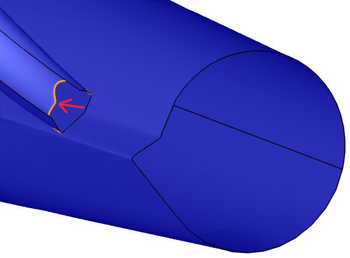
Intersection of Side A1/B1 with Inlet/Outlet |
|
Cut-water Side A1/B1 face intersects with Inlet/Outlet face. Inlet/Outlet is a virtual face bordering the Volutes's Flow domain. The intersection affects volumetric meshing of the Flow domain, which may result in very small mesh entities and in a non smooth surface in these regions. Generally, the intersection is very small and hardly visible in 3D-model. |
Any parameter modification of the Fillet Cut-water affects the geometry of the side patches. Use automatic Surface transition. |
The cut-water cannot be created because the spiral wrap angle is too low (minimum: ...). |
|
A minimum spiral wrap angle is necessary for cut-water creation. |
Increase spiral warp angle at least to the given minimal value. |
Cutwater is self-intersecting. |
|
Cut-water faces intersect each other.
|
The problem might have various reasons. Therefore, modify spiral, diffuser or cutwater design. E.g. define a flat radius progression at the start of spiral development areas, or change angular position / radial offset of the cutwater. |
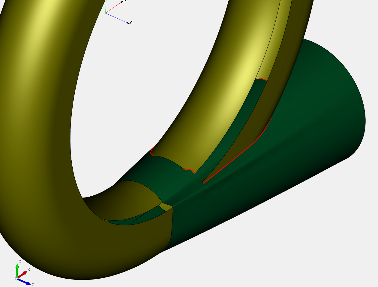
Multiple intersection curves between spiral and diffuser. |
|
Spiral and diffuser may have multiple intersection curves. (red)
|
This problem can be solved by manipulating the spiral start position. A single intersection curve is required for generation of sharp and fillet cut-waters. |
3D-Error: Could not create bounded surface for Cut-water! |
|
Parameter side position is disadvantageous. |
The side position should not be too low when edges are rounded. |
3D-Error: Creation of Cut-water failed! Possibly, the fillet radius is too large. |
|
[for asymmetric volutes] Fillet cannot be created because intersection curve of spiral and diffuser is wavy.
|
Modify the Position of end shape in the Diffuser dialog to avoid wavy intersection curve. |
[for asymmetric volutes] Fillet cannot be created because intersection curve of spiral and diffuser is tangential to the sharp diffuser edge.
|
Modify Spiral start position
|
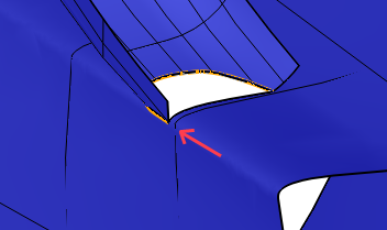
Creating fillet cutwater requires intersection between diffuser and spiral contour. |
|
There is no intersection of original spiral surface and diffuser surface. The fillet cut-water is generated along this intersection curve. |
The shape of spiral and diffuser determine the intersection. The diffuser shape is additionally influenced by the "Radial offset" (reduce if possible) and the "Diffuser base form factor" (enlarge if possible). |