|
<< Click to Display Table of Contents >> Inducer |
  
|
|
<< Click to Display Table of Contents >> Inducer |
|
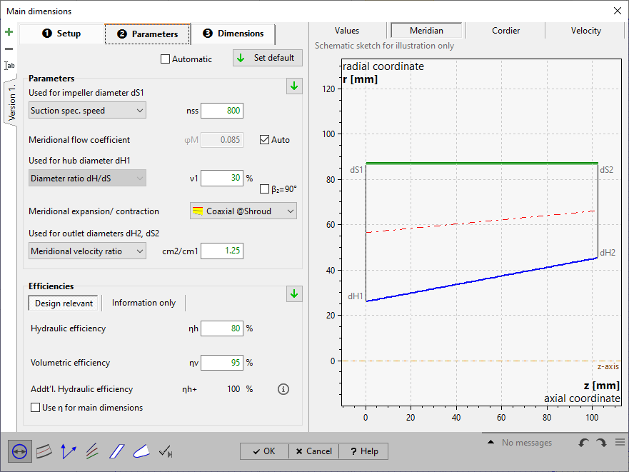
Inducers are placed in front of centrifugal pump impellers normally in order to improve the suction performance (reduce NPSHR) of the pump.
For inducers the inlet section is the primary one. The important suction diameter dS1 is calculated using the meridional flow coefficient φm:
![]()
In CFturbo the so called Brumfield curve is used to estimate an appropriate φm value to achieve a required level of suction performance. Input values is the suction specific speed nss:
![]() (or the US definition Nss, see Preferences/Units/Other)
(or the US definition Nss, see Preferences/Units/Other)
The Brumfield curve can be displayed and also modified if necessary by clicking on the function button just right of the nss edit field.
The φm value can be calculated automatically from the given nss value or modified manually. There is a limit of φm ≈ 0.06, lower values will result in backflow at blade tip and cavitation induced flow instability.
Alternatively you can specify the rel. inlet flow angle β1S or the meridional flow coefficient φm directly. Furthermore the parameters for classic axial pump design could be used alternatively.
The inlet hub diameter dH1 is calculated using the diameter ratio ν1:
![]()
Typical for inducers is a constant tip (shroud) diameter. The hub diameter can increase from inlet to outlet slightly in order to use centrifugal effect for energy transmission. The meridional velocity ratio between inlet and outlet can be used to estimate the outlet cross section:
![]()
Alternatively the diameter ratio ν2=dH2/dS2 at outlet similar to the inlet side can be used.