|
<< Click to Display Table of Contents >> Parameters Fan |
  
|
|
<< Click to Display Table of Contents >> Parameters Fan |
|
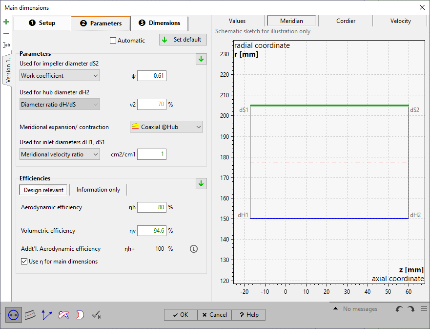
On page Parameters you have to put in or to modify parameters resulting from approximation functions in dependence on specific speed nq or flow rate Q.
See Approximation functions.
For details of how to handle the parameter edit fields please see Edit fields with empirical functions.
|
Parameter and efficiency values can be handled manually or can be switched to automatic update by the checkbox on top of the page. Then the default values are used always, even after design point modifications (see Global setup). |
If the automatic mode is not selected the current default values can be specified by one of the following options:
|
globally by the button on top of the page |
|
regionally by the default button within the Parameters or Efficiency region |
|
individually by the default button within the input field when selected |
The panel Parameters allows defining alternative parameters in each case for the calculation of the following impeller diameters:
|
||||
|
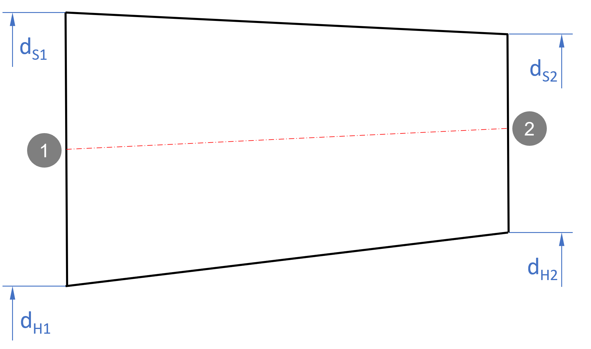
For dS2-calculation
Work coefficient ψ (= pressure and head coefficient) |
▪dimensionless expression for the specific energy:
0.7 ...1.3 centrifugal impeller 0.25...0.7 mixed-flow impeller 0.1 ...0.6 axial impeller ▪high → small dS2, flat characteristic curve |
Specific diameter δ |
▪according to Cordier diagram (see Dimensions) |
Flow coefficient φ |
▪dimensionless flow rate ▪high → small dS2, flat characteristic curve |
For dH2 calculation
Diameter ratio dH2/dS2 |
Can be estimated under assumption β2 = 90° @ hub and cu·u = const. by:
|
For dS1/dH1-calculation
Meridional velocity ratio cm2/cm1 |
|
||
Diameter ratio dH1/dS1 |
|
||
|
strictly axial |
dH2 = dH1 and dS2 = dS1 |
|
|
const. at hub |
dH2 = dH1 |
|
|
const. at mid-span |
dM2 = dM1 |
|
|
const. at shroud |
dS2 = dS1 |
|
In panel Efficiency you have to specify several efficiencies. You have to distinguish between design relevant efficiencies and efficiencies used for information only:
Design relevant
•total-total efficiency ηtt
•volumetric efficiency ηv
•additional total-total efficiency ηtt+ (displayed for information only, see Global setup)
Information only
•mechanical efficiency ηm
•motor efficiency ηmot
The additional total-total efficiency ηtt+ is used for impeller dimensioning in order to compensate additionall flow losses .
The losses resulting in energy dissipation from the fluid form the internal efficiency.
![]()
Impeller and mechanical efficiency form the overall efficiency (coupling efficiency) of the stage ηSt.
When considering motor losses additionally the overall efficiency of the stage incl. motor ηSt* is defined.
|
PQ: power output, see above PD: mechanical power demand (coupling/ driving power) |
|
Pel: electrical power demand of motor |
The following summary illustrates the single efficiencies and their classification:
classification |
efficiencies |
Relevant for impeller design |
||
stage |
impeller |
ηtt+ |
additional total-total |
yes: for energy transmission |
ηtt |
total-total |
|||
ηV |
volumetric |
yes: for flow rate |
||
|
ηm |
mechanical |
no: for overall information only |
|
stage incl. motor |
electrical |
ηmot |
motor |
|
The obtainable overall efficiency correlates to specific speed and to the size and the type of the impeller as well as to special design features like bypass installations and auxiliary aggregates. Efficiencies calculated by approximation functions are representing the theoretical reachable values and they should be corrected by the user if more information about the impeller or the whole pump are available.
The hydraulic efficiency (or blade efficiency) describe the energy losses within the pump caused by friction and vorticity. Friction losses mainly originate from shear stresses in boundary layers. Vorticity losses are caused by turbulence and on the other hand by changes of flow cross section and flow direction which may lead to secondary flow, flow separation, wake behind blades etc.
The volumetric efficiency is a quantity for the deviation of effective flow rate Q from total flow rate inside the impeller ![]() :
:
![]() (rising with decreasing tip clearance)
(rising with decreasing tip clearance)
The mechanical efficiency mainly includes the friction losses in bearings and seals:
![]() (rising with impeller size)
(rising with impeller size)
Total-total and volumetric efficiency are most important for the impeller dimensioning because of their influence to ![]() and/or
and/or ![]() . The mechanical efficiency is affecting only the required driving power of the machine.
. The mechanical efficiency is affecting only the required driving power of the machine.
If the check box "Use η for main dimensions" is set, then main dimension calculation is done on the basis of Yeff= 0.5(Y/η+Y). Otherwise Y - specific work without losses - is used.
In the right area of the register Parameter you can find again some calculated values for information:
Required driving power |
|
Power loss |
|
Internal efficiency |
|
Stage efficiency |
|
Stage efficiency incl. motor |
|
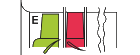
Assembly |
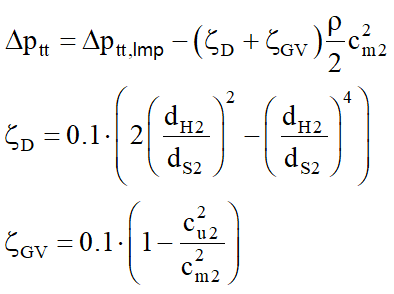
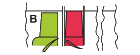
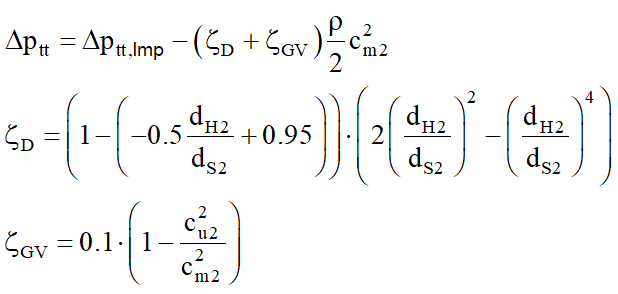
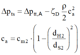
Pressure difference |
Remark |
|
|
inline installation, resistance coefficients according to Wallis |
|
|
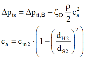
inline installation, Carnot type diffuser resistance coefficients according to Wallis |
|
|
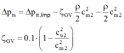
inline installation, swirl assumed to dissipate in duct → pseudo total-to-total pressure rise resistance coefficients according to Wallis |
|
|
exhaust installation potential pressure recovery in exhaust jet not taken into account |
|
|
|
|
|
|
|
|