|
<< Click to Display Table of Contents >> Dimensions |
  
|
|
<< Click to Display Table of Contents >> Dimensions |
|
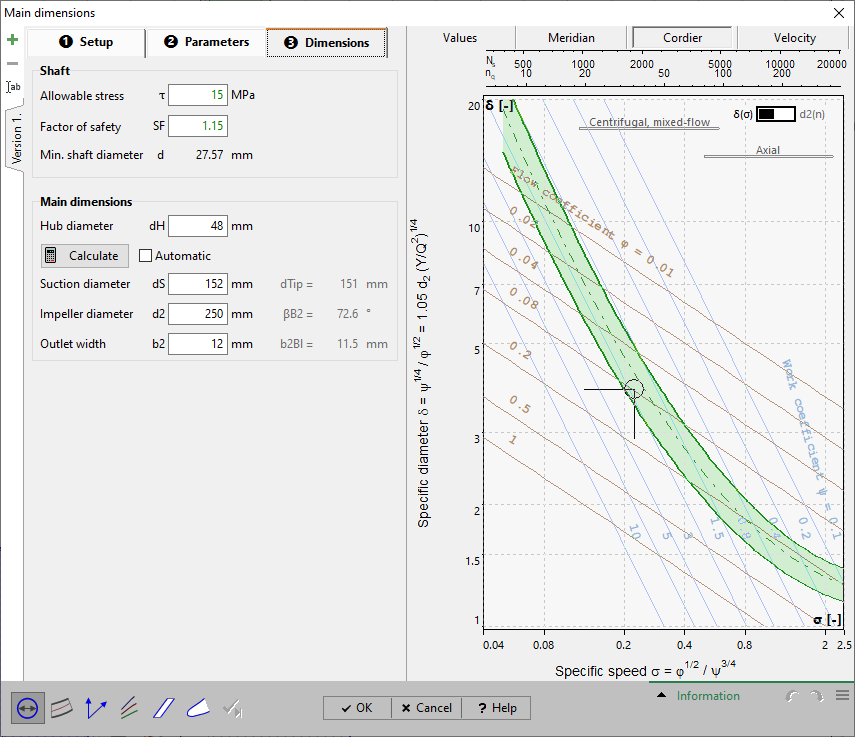
In the panel Shaft, the required shaft diameter is computed.
¢ Shaft/ Hub
The hub diameter is determined by the user and depends on the shaft-hub connection.
The main dimensions can be seen on Main dimensions panel. They can be recomputed by pressing the Calculate-button. The computation is based on "Euler's Equation of Turbomachinery", on the continuity equation and the relations for the velocity triangles as well as on the parameters given in the tab sheets Setup and Parameters.
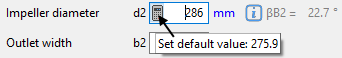
Individual main dimensions can be calculated separately using the button inside the value field.
You may accept the proposed values or you can modify them slightly, e.g. to meet a certain normalized diameter.
In case the checkbox Automatic is activated a new calculation will accomplished after any change of parameter. Then the manual alteration of the main dimensions is not possible.
Due to the Euler equation the impeller diameter d2 and the blade angles βB2 are coupled (see Outlet triangle). Lower d2 values result in higher βB2 (higher blade loading) and vice versa. For that reason the resulting average βB2 value is displayed for information right beside the calculated/ specified d2 value.
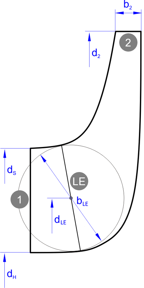
![]()
Neighboring components
In specific cases the dimensions of the neighboring components at inlet and/ or outlet can be used to get exactly matching geometry.
![]()
This feature is available only for explicitly uncoupled components or side-by-side impellers.
In the right panel of any tab sheet an information panel is situated, which holds the computed variables in accordance to the actual state of design, the resulting Meridional section as well as the Cordier-Diagramm with the location of the best point. These three sections can be chosen by the appropriate soft buttons in the heading.
In the Value section the following variables are displayed for information which result from calculated or determined main dimensions:
Flow properties at: |
density ρ |
Velocity triangles at: |
velocities u, cm, cm*, cu, c, wu, w |
Work coefficient |
|
Flow coefficient |
|
Meridional flow coefficient |
|
Specific diameter |
|
Tangential force coefficient |
|
Outlet width ratio |
b2/d2 = 0.01...0.15 |
Diameter ratio |
dS/d2 |
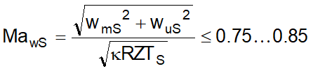
Relative Tip Mach number |
|
Machine Mach number |
|
Degree of Reaction |
|
Reynolds number |
with d1 = highest diameter at inlet |
with b1 = width at inlet |
|
with d2 = highest diameter at outlet |
|
with b2 = width at outlet |
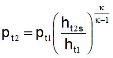
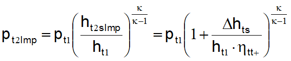
In the impeller outlet (cross section 2) two different total pressure values are given: pt2 and pt2Imp. This is based upon the following assumption: All non-rotating components of the project are considered as being loss-less. An additional efficiency can be defined in the global setup. Additional losses connected to this additional efficiency are considered within the impeller. That is to say, straight after the trailing edge an adiabatic expansion takes place reducing the total pressure of the impeller pt2Imp to the value at the inlet of the next non-rotating component pt2. In accordance to following diagram these two different pressure values are calculated (assuming perfect gas behavior) by:
|
and |
|
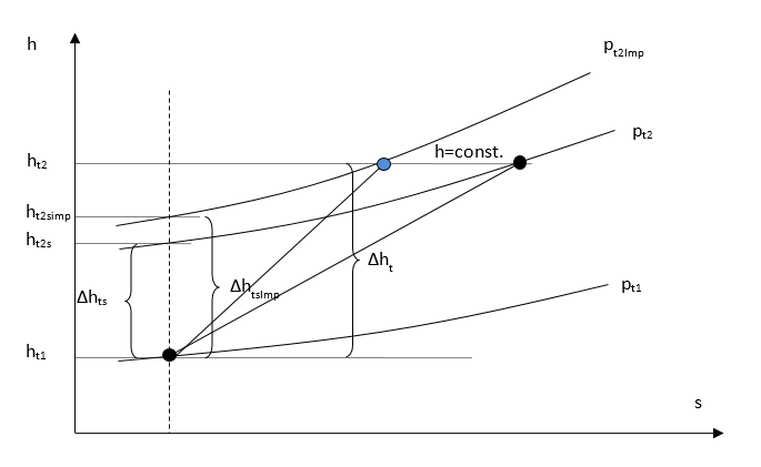
All thermodynamic values are calculated on the basis of the total pressure pt2Imp in cross section 2.
If a stator is located prior the impeller, boundary conditions for the determination of the main dimensions will be calculated on the basis of the thermodynamic state at the outlet of this stator. In case of an undefined thermodynamic state at this location the inlet boundary conditions (i.e. total pressure and temperature as well as swirl) will be taken from the global setup and a warning is generated.
It might be that for the chosen configuration of global setup and main dimensions a reasonable thermodynamic state cannot be calculated. This may be the case if e.g. the mass flow is too high for the chosen cross sections. Then again a warning is generated.
The Meridional preview is based on the until now designed main dimensions.
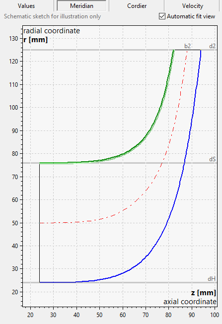
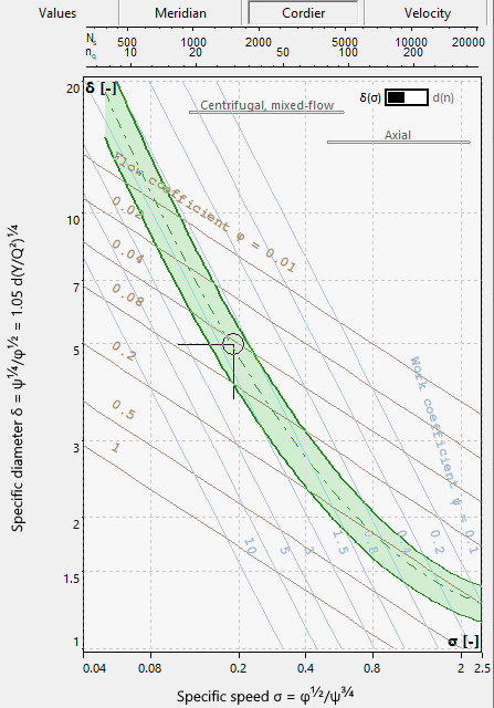
The Cordier diagram can be used for checking the impeller diameter d2.
See Cordier.
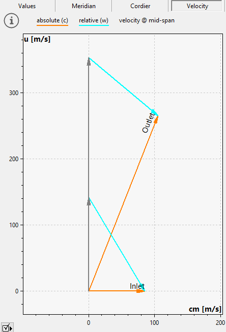
The Velocity triangles are the result of a mid-span calculation and are based on the design point and the main dimensions.
Problem |
Possible solutions |
|---|---|
Thermodynamic state cannot be calculated at inlet/outlet. Possible reason: choked flow. Consider change of main dimensions or global setup. |
|
The dimensions might be too tight for the specified mass flow and inlet conditions. In other words the mass flow is higher than the choked mass flow rate for the particular inlet condition and the respective cross section. |
Increase the dimensions (width, diameters etc.) or change the Global setup (e.g. decrease mass flow, increase pressure, decrease temperature). |
 .
.