|
<< Click to Display Table of Contents >> Parameters |
  
|
|
<< Click to Display Table of Contents >> Parameters |
|
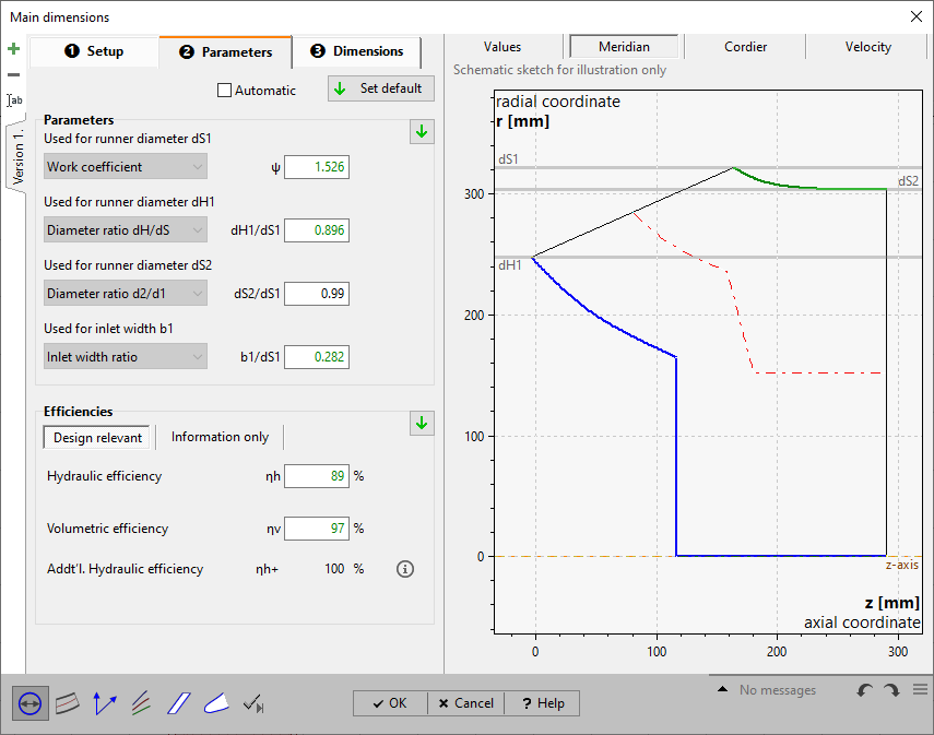
On page Parameters you have to put in or to modify parameters resulting from approximation functions in dependence on specific speed nq or flow rate Q.
See Approximation functions.
For details of how to handle the parameter edit fields please see Edit fields with empirical functions.
|
Parameter and efficiency values can be handled manually or can be switched to automatic update by the checkbox on top of the page. Then the default values are used always, even after design point modifications (see Global setup). |
If the automatic mode is not selected the current default values can be specified by one of the following options:
|
globally by the button on top of the page |
|
regionally by the default button within the Parameters or Efficiency region |
|
individually by the default button within the input field when selected |
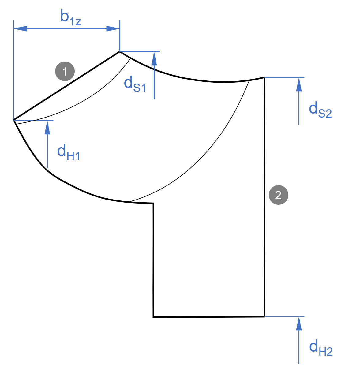
The panel Parameters allows defining alternative parameters in each case for the calculation of the following impeller diameters:
|
||||
|
For dS1-calculation
Work coefficient ψ |
▪dimensionless expression for the specific energy:
|
For dH1 calculation
Diameter ratio dH1/dS1 |
|
For dS2 calculation
Diameter ratio dS2/dS1 |
|
For b1z calculation
width ratio b1z/dS1 |
|
In panel Efficiency you have to specify several efficiencies. You have to distinguish between design relevant efficiencies and efficiencies used for information only:
Design relevant
•hydraulic efficiency ηh
•volumetric efficiency ηv
Information only
•mechanical efficiency ηm
The losses resulting in energy dissipation from the fluid form the internal efficiency.
![]()
Internal and mechanical efficiency form the overall efficiency (coupling efficiency) of the stage ηSt.
|
PQ: Runner power PD: Power output (coupling/ driving power) |
The following summary illustrates the single efficiencies and their classification:
classification |
efficiencies |
Relevant for impeller design |
||
stage |
internal |
ηh+ |
additional hydraulic |
yes: for energy transmission |
ηh |
hydraulic |
|||
ηV |
volumetric |
yes: for flow rate |
||
|
ηm |
mechanical |
no: for overall information only |
|
The obtainable overall efficiency correlates to specific speed and to the size and the type of the runner as well as to special design features like bypass installations and auxiliary aggregates. Efficiencies calculated by approximation functions are representing the theoretical reachable values and they should be corrected by the user if more information about the impeller or the whole turbine are available.
The hydraulic efficiency (or blade efficiency) describe the energy losses within the turbine caused by friction and vorticity. Friction losses mainly originate from shear stresses in boundary layers. Vorticity losses are caused by turbulence and on the other hand by changes of flow cross section and flow direction which may lead to secondary flow, flow separation, wake behind blades etc.
The volumetric efficiency is the ratio of the flow striking the runner and the flow through the turbine Q:
The mechanical efficiency mainly includes the friction losses in bearings and seals:
Hydraulic and volumetric efficiency are most important for the runner dimensioning because of their influence to and/or . The mechanical efficiency is affecting only the actual output power of the machine.
In the right area of the register Parameter you can find again some calculated values for information:
Torque |
|
Actual power output |
PD = PQ·ηSt |
Power loss |
|
Internal efficiency |
|
Stage efficiency |
|