|
<< Click to Display Table of Contents >> Model display (top) |
  
|
|
<< Click to Display Table of Contents >> Model display (top) |
|
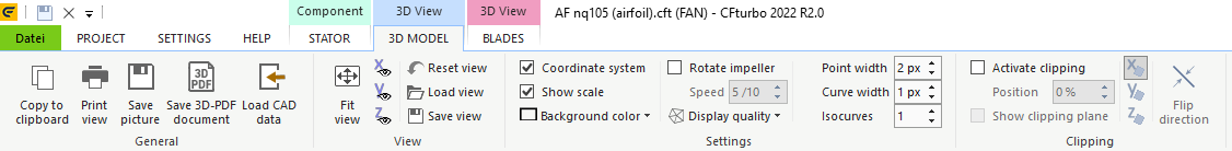
3D MODEL
The following actions are available by the buttons of the 3D Model tab. They are used for visualization only and do not affect the geometry model.
|
Copy representation to clipboard |
|
Print representation |
|
Save representation as PNG, JPG, GIF or BMP |
|
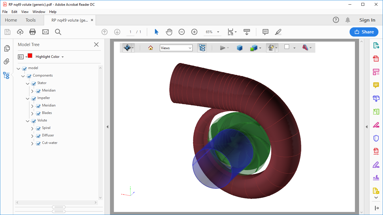
Save representation as 3D-PDF Visible 3D-model data is transfered to a PDF-document, enabling the user to distribute or archivate a 3D-representation of CFturbo-models. The PDF-document contains a 3D-viewer, including a model-tree as well as various 3D-capabilities (e. g. measuring, clipping, display options). It can be opened with PDF-viewers supporting 3D-content (e. g. Adobe® Acrobat® Reader, not possible in internet-browsers without certain plugins). If the PDF-document is opened in a PDF-viewer and a static picture is shown instead of a 3D-model, then: 1) ensure using a PDF-viewer supporting 3D-content An example of a 3D-PDF visualized in Adobe® Acrobat® Reader DC is shown below:
|
|
Import external 3D geometry for visualization The 3D Import enables the user to view 3D data in IGES, STEP, STL, Parasolid and BREP format or of CFturbo-projects (*.cft) e.g. for comparison with the current design or for redesigning. Geometry data is shown in the 3D Model and can be transformed and exported. If the import consumes a lot of time, a lower resolution can be selected (see "Settings" below). |
|
Fit view (zoom all geometry to visible region) |
|
Viewing direction in positive or negative (<ñ>) x-axis direction |
|
Viewing direction in positive or negative (<ñ>) y-axis direction |
|
Viewing direction in positive or negative (<ñ>) z-axis direction |
|
Reset view (default position) |
|
Load view from file |
|
Save current view to file |
|
Switch coordinate system on/off |
|||
|
Switch scale system on/off |
|||
|
Set background color |
|||
|
A uniform rotation of the impeller around the z axis can be generated, whereby the velocity can be influenced by the track bar. |
|||
|
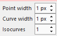
Select resolution of curves and surfaces (affects display) |
|||
|
||||
|
||||
|
||||
|
|
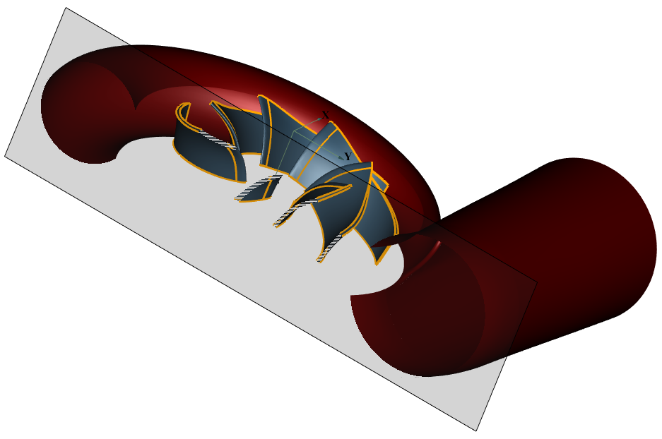
A clipping plane for x=const., y=const. or z=const. can be defined and optionally displayed. The position of the clipping plane can be adjusted.
The direction of clipping (visible clipping side) can be switched.
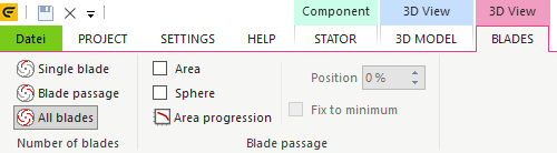
BLADES
These actions are used for visualization only and do not affect model geometry.
Please note: The following options refer to the currently selected component of the project.
|
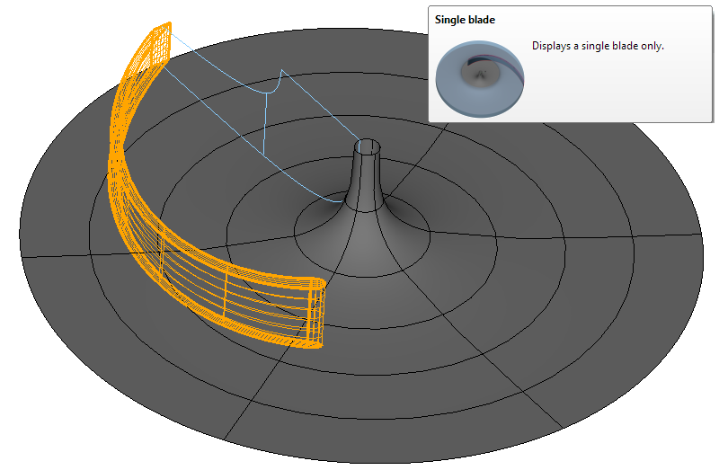
Single blade
|
||
|
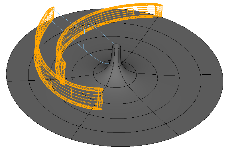
Blade passage
Display a single blade passage bordered by 2 neighboring blades.
|
||
|
All blades
Display all blades of the selected impeller or vaned stator.
|
||
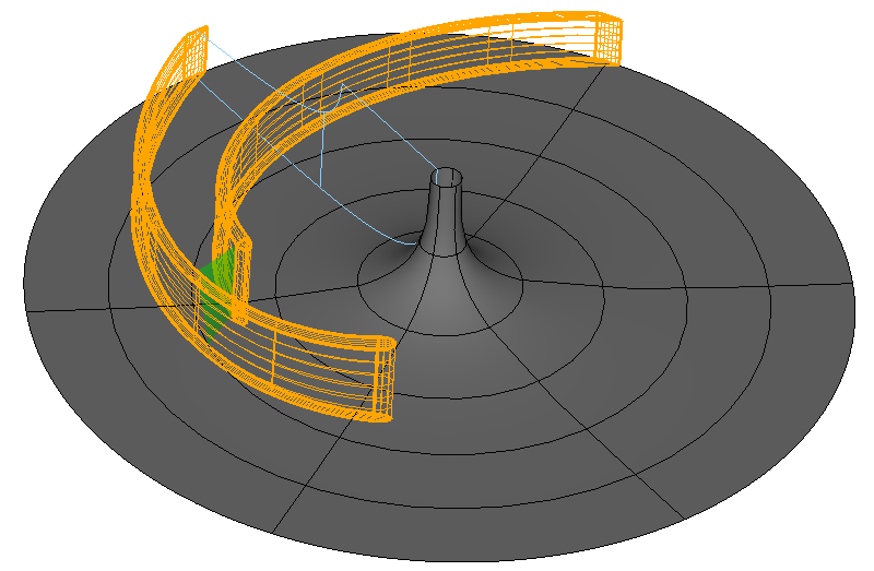
Area
Display an approximately perpendicularly flown through area between hub, shroud and two neighboring blades for the currently selected component. The position of this area can optionally be fixed to the location of the throat area (Fix to minimum). Otherwise, it can be slided to any reasonable position within the blade to blade channel with the help of the track bar Section Position.
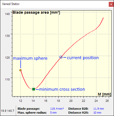
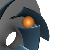
By pressing the button Show progression a window is opened, in which the value of the cross section is displayed in dependence on the position (see here for changing position variables) between leading edge and trailing edge. The current position as well as that of the throat area and the maximum sphere diameter are marked with special symbols. In the lower part of the window some measures for the current position are displayed.
|
|||
|