|
<< Click to Display Table of Contents >> Model tree (left) |
  
|
|
<< Click to Display Table of Contents >> Model tree (left) |
|
|
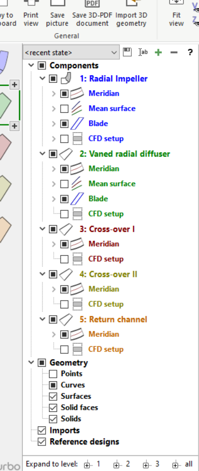
The model tree contains all available geometry parts listed in a tree structure, whereby their visibility can be switched on or off alternatively. All visible elements are exported, if the model is saved as IGES, STEP, STL, Parasolid or BREP - see Export. |
The elements selected in the model tree are highlighted in the 3D view. The selection can be cleared by pressing the <Esc> key.
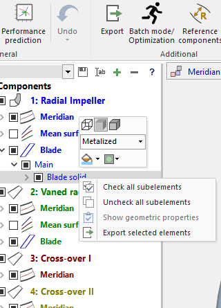
The attributes can be defined by right click:
|
• Display mode: Wireframe, Shaded surface, Shaded surface with edges • Material • Color and transparency • Check/ uncheck all sub-elements of the selected element • Show geometric properties of selected element in extra dialog: ovolume, density, mass, center of gravity and static moments of inertia for solids oarea for surfaces olength for edges • Export selected element as IGES, STEP, STL, Parasolid or BREP. Imported geometry will be exported in its transformed state (this option is not available for STL imports) |
|
For elements in the Imports section only: • removes selected element(s) from model tree and 3D view • renames selected element inside model tree |
The model tree has 3 main sections:
1) Section Components
contains all components of the project with the following sub elements:
If an element contains child elements, it can be expanded by clicking on the collapsed element symbol (![]() ).
).
Each single element without child elements can be selected (![]() ) or unselected (
) or unselected (![]() ).
).
Each single element with child elements can have 3 states:
|
|
|
|
|
|
An element is visible in the 3D view, if it is selected and all its parent elements are also selected.
Note: If the <Ctrl> key is pressed while selecting an element, all child elements are selected, too!
2) Section Geometry
contains all basic geometrical types:
•Points
•Curves
•Surfaces
•Solid faces
•Solids
This allows:
•to select all objects of a certain geometrical type. In the 3D view, only those elements become visible, whose parent elements are selected also.
•to modify the display properties of all currently visible objects of a certain geometrical type.
3) Sections Imports and Reference designs
These sections contain imported geometric models: imported 3D models from neutral 3D file formats and CFturbo components of reference projects.
Visibility and render properties for imported models can be modified in the same way as for models of section Components.
Selecting a model tree node of an imported model enables the 3D-transformation of the entire model. For that purpose the panel Transformation is displayed at the bottom side of the model tree. This can be used to align imported models with the project model for visual comparisons of the model shapes.
|
The Transformation panel allows the application of five different types of geometric transformations: •Translations can be applied iteratively along the coordinate axes. •Rotations can be applied iteratively around the coordinate axes. •Uniform model scaling is applied in absolute (percentage) terms. •Mirroring is toggled for the models coordinate system in all three coordinate directions. •Z-Axis alignment applies to the selection of a single or multiple face(s) containing rotational properties (e. g. cylinder, cone) and aligns the related rotational axis collinear to the global z-axis. |
To apply a transformation to the selected parts, select a transformation type, set its parameters and hit <Enter>.
The model transformation can be reset to the state which it was imported with by clicking the reset button on top right.
Useful transformations for an imported model can be saved for later use by exporting the model with its current transformation via the context menu (Export).
Model states contain the properties of all tree elements (except imports). Several model states can be managed via the controls above the model tree.
|
Select existing model state |
|
Save model state |
|
Rename selected model state |
|
Add new model state |
|
Delete selected model state |
The following predefined model states cannot be modified:
•"Default" |
The default model state |
•"Default + CFD setup" |
The default model state with CFD setup visible |
•"Flow domain solids" |
Only solids are visible that belong to the flow domain |
•"Material domain solids" |
Only solids are visible that belong to the material domain |
•"Component colors" |
Every component is displayed with the color defined in the Components view |
For performance reasons, model states do not contain the state of each individual 3D object, but only to the level of distinction between different geometrical types (points, curves, surfaces). Therefore, e.g. all curves that belong to a "Curves" object share the same properties.