|
<< Click to Display Table of Contents >> Export |
  
|
|
<< Click to Display Table of Contents >> Export |
|
► PROJECT | Export ![]()
The Export offers the designed geometry to be exported in standard file formats or for several CAE applications.
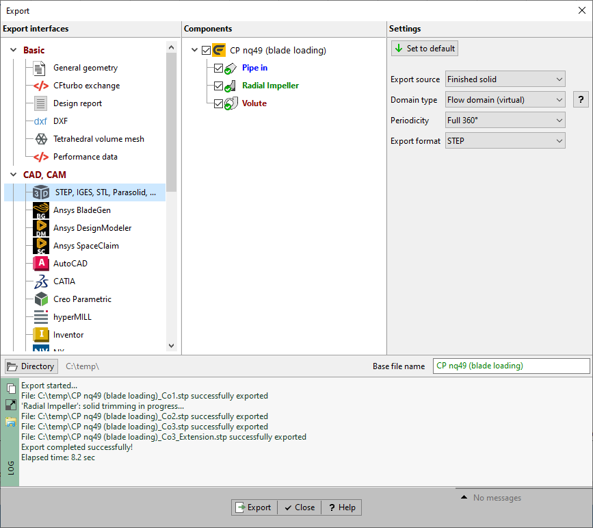
For geometry export you have to:
1.Select interface in panel Interfaces
2.Select component(s)
3.Set export settings
4.Press Export data button
Available interfaces are grouped into three blocks: Basic, CAD, CAM and CFD, FEA.
Generally, there are three export types available:
•3D model export
all parts of the 3D model according to a pre-defined model state
•Predefined 3D model export
flow domain or material domain as solid faces
•Point based export
pre-defined set of points/ splines (independent of the 3D model)
For 3D model exports, the formats IGES, STEP, STL, Parasolid and BREP can be selected. The point density can be configured in the Model settings/ 3D model of each component (Impeller, Stator, Volute). The export unit is mm always.
For point based exports, the point density and export unit can be configured in the Model settings/ Point export of each component (Impeller, Stator, Volute). If the blade shape is ruled surface then points of mean lines as well as profiles (pressure and suction side) are not affected by the model settings for the point based export.
Please note: The results of surface-based operations, e.g. fillets, cannot be exported to point-based formats.
The list contains all components of the project. If the interface supports multi-component export then you can select multiple components, otherwise only a single one. For 3D model exports, no component can be selected because the geometry to be exported is defined by its visibility in the 3D model.
Some of the interfaces support special component types only, e.g impellers. Therefore some of the components could be deactivated.
Additional parameters depending on the selected export interface can be specified on the right side of the window.
Above the log area the export destination and the base name of exported files can be specified.
By pressing the Export data button the export procedure is started. Some logging information are displayed in the log area.
For some CAD and CFD applications the exported geometry can be opened in the target application automatically. The product version has to be selected from a list or the installation directory can be defined manually.

|
Problem |
Possible solutions |
|---|---|---|
CFD setup |
Blade tip projection to casing recommended (see CFD setup). |
|
Blade tip projection not accomplished. |
Check "Blade projection" in CFD setup. |
|
Gap between leading/trailing edge and inlet/outlet required. |
||
Some space around blade edges is required for meshing. This can be generated by creating a CFD extension or by selecting a neighbouring stator component. Note for TurboGrid: a vaneless stator has to be selected, which has to be considered as part of the rotating domain in TurboGrid. |
Try to increase the distance between leading/ trailing edge and meridional inlet/ outlet by a) moving leading/ trailing edge in meridional contour if edge is not fixed on inlet/ outlet. b) selecting a neighbouring stator if possible. or c) activating CFD-Extension in CFD setup/ Extension. |
|
Gap between leading/trailing edge and inlet/outlet recommended. |
||
Some space around blade edges is recommended. |
Try to increase the distance between leading/ trailing edge and meridional inlet/ outlet by a) moving leading/ trailing edge in meridional contour if edge is not fixed on inlet/ outlet. or b) activating CFD-Extension in CFD setup/ Extension. |
|
Small gap between blade/leading edge and inlet/outlet may cause problems. |
||
See message. |
Try to increase the distance between leading/ trailing edge and meridional inlet/ outlet by a) moving leading/ trailing edge in meridional contour if edge is not fixed on inlet/ outlet. or b) activating CFD-Extension in CFD setup/ Extension (only for impellers). |
|
|
||
Finishing |
Beware: "Solid" and "Solid faces" are handled differently in various target systems. |
|
To be taken into account if a mixed selection of solids and solid faces was selected in the 3D model tree. |
- |
|
|
||
Blades |
Blades with thickness definition "perpendicular to mean surface" are not supported. |
|
See message. |
Choose another blade thickness definition method (see thickness definition in Blade Profiles). |
|
|
||
Volute |
"Flow domain" export may not work. |
|
The STEP export of "Flow domain.Solid" or "Flow domain.Solid faces.Spiral" might be defective if the spiral face spans a wrap angle of 360°. This occurs for internal volutes. |
Select "Spiral.Surface" instead in the 3D model tree. |
|
|
||
Model |
Model geometry does not fit a cube of size (-500, -500, -500) to (500, 500, 500). |
|
A geometry can be correctly represented only if it is fully included in a cube between the points (-500,-500,-500) and (500,500,500) due to a Parasolid™ library limitation. |
Change length unit in export parameters dialog for selected export interface. |
|
Current point export settings may cause problems in Autodesk Inventor due to high number of points. |
||
See message. |
Change number of points in Model settings/Point export. |
|
|
||
General
|
Completion of all design steps required. |
|
Only for CFD-Applications. One or more design steps were not finished. |
Complete all design steps. |
|
Special license for this interface required. |
||
License for this interface not found. |
Check the license information in SETTINGS/ Licensing. |
|
Export not possible due to license restrictions. |
||
The corresponding module is not licensed or CFturbo is running with a trial license. |
Only designs corresponding with licensed modules or unmodified default examples using a trial license can be exported. |
|
Material domain is not available |
||
Components without material domain are not supported by this interface. |
The material domain is created with •Hub/Shroud materials designed in the Meridian design step •Blade solids For unvaned stators, the material domain cannot be created because hub/shroud solids are not connected by the blade solid. |
|
Model state contains no geometry for export. |
||
See message. |
Select via "Set parameters" a proper model state containing desired parts to be exported. |
|
Meshing process ran out of memory. |
||
A too fine-grained mesh was produced. This resulted in exceeding virtual memory. |
Adjust the triangulation parameters, especially minimum and maximum element length.
Or if you are using the 32 bit version of CFturbo change to 64 bit. |
|
Invalid viscosity value. |
||
See message. |
Set a valid viscosity value in fluid manager. |
|
Some objects didn't get meshed properly: [Face names] |
||
The exported mesh is not watertight due to some invalid areas inside the mesh. These areas are equivalent to the specified faces in the warning message. |
Check the specified faces in the 3D-model due to invalid geometry. Vary the meshing parameters. |
|
The exported mesh has overlapping triangles. In this case, the number of overlapping triangles is specified in the warning message. Usually, there are just a few triangles overlapping. |
Vary the meshing parameters (finer as well as coarser parameters might solve the overlapping). If it can't be resolved through varying meshing parameters, then attention should be paid on the generation of the volumetric mesh in CFD-applications. Mesh irregularities might be handled during the pre-processing, too. |
|