|
<< Click to Display Table of Contents >> Blade profiles |
  
|
|
<< Click to Display Table of Contents >> Blade profiles |
|
► IMPELLER | Blade profiles ![]()
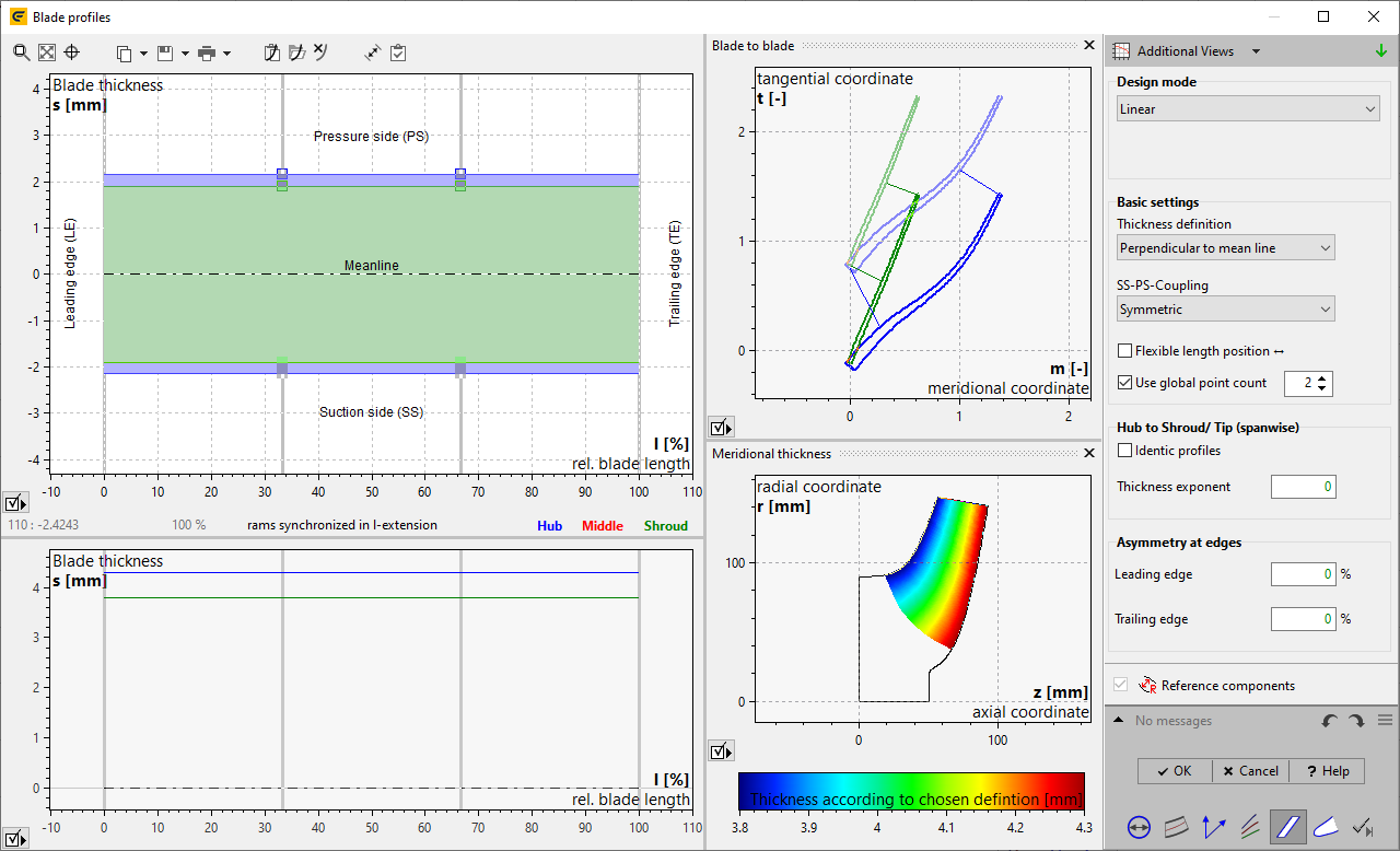
To create blade profiles (main and splitter) the blade thickness distribution for the hub and the shroud profile is used. By default the thickness is defined at leading edge, at trailing edge and at the control points of the blade. For the initial CFturbo-design, typical values in dependence on the impeller diameter d2 are used (see Approximation functions).
2 impeller types have special thickness distribution:
•Waste water pumps have very high thickness at leading edge to avoid solid attachments. Starting from 20% of the blade length the thickness is constant up to the trailing edge.
•Inducer pumps have very low thickness at leading edge to improve suction performance. The very small leading edge thickness is increasing up to 40%...80% of pitch (t=πd/nBl) to achieve constant blade thickness. The thickness distribution is asymmetric and sharpen at the suction side only.
The representation of the thickness distribution is made along the relative blade length (0 = leading edge, 1 = trailing edge).
|
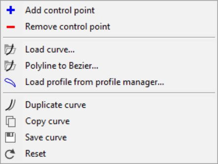
Each thickness curve has a popup menu (right click on curve) to handle its properties. "Polyline to Bezier" converts a loaded polyline into a Bezier curve, where the number of desired Bezier points can be specified. "Load profile from profile manager" can be selected to use a pre-defined thickness distribution. |
|
"Convert to Bezier" is available for polyline thickness definition only and converts it to a Bezier curve very similar to "Polyline to Bezier". |
|
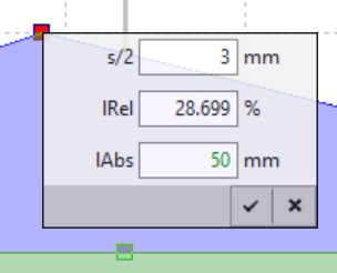
The position of the control points can be changed by moving them with the mouse or by entering specific values by right-clicking. For the value input, the relative or absolute position along the blade can be used alternatively. |
The following general properties of the profile design can be specified on the right side:
Linear
Linear interpolation between control points
Freeform
Bezier curves are used for the thickness distribution
LE / TE rounded: Leading and trailing edge can be rounded optionally. If a polyline was loaded this option is determined automatically and cannot be modified.
Linked to Main
Only for splitter blades: splitter profile is linked to main profile
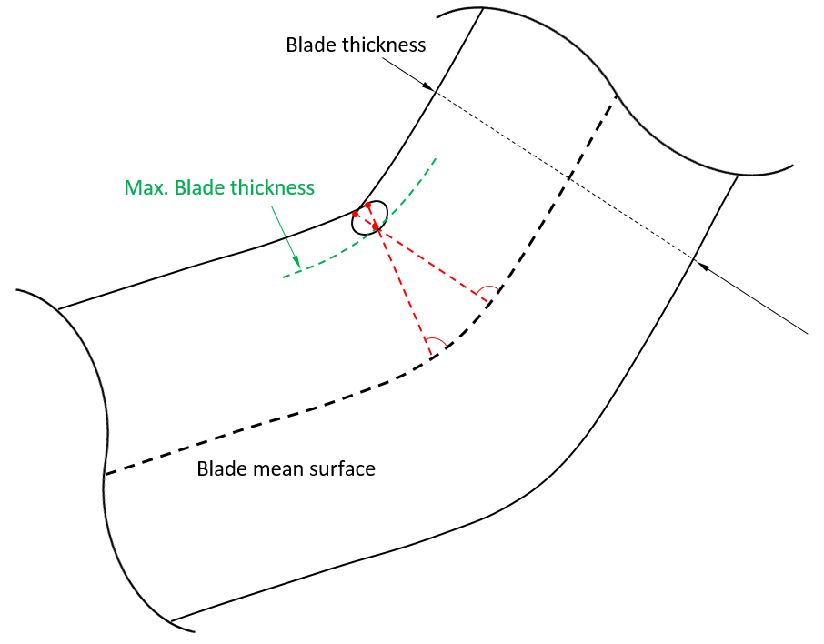
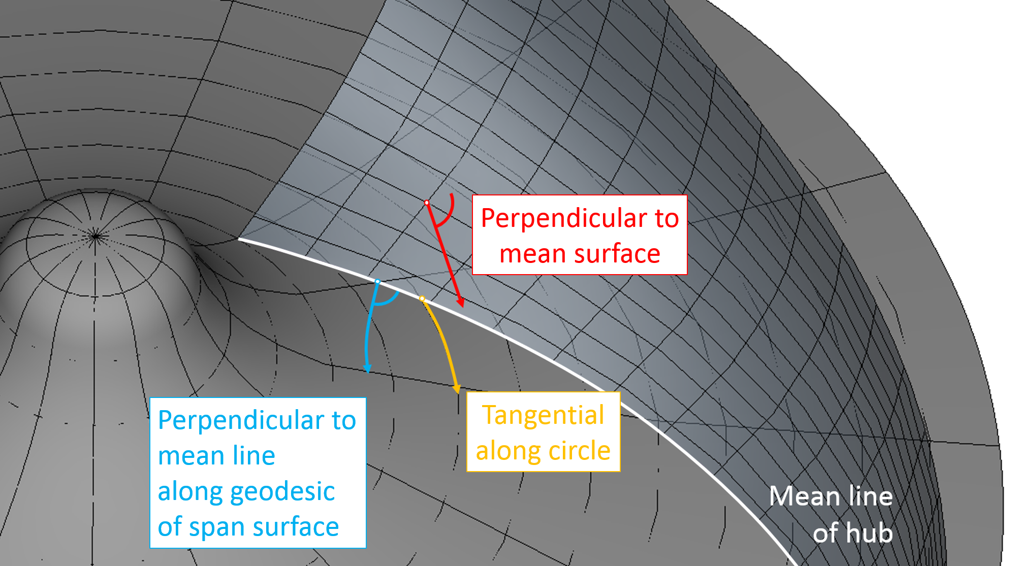
Thickness definition specifies the way of adding blade thickness values to both sides of the blade mean line to create the pressure and suction sides of the blade. Three types of method are supported:
Perpendicular to mean surface
After creating the mean surface from all mean lines, the thickness values are added along surface normal. Naturally, this method depends on all mean lines.
Perpendicular to mean line (recommended)
Thickness values added orthogonal to mean line inside rotational surface defined by span. Compared to method above, this definition only depends on the mean line/span itself. Therefore it provides higher stability in trimming with hub/shroud especially for highly curved blade geometry.
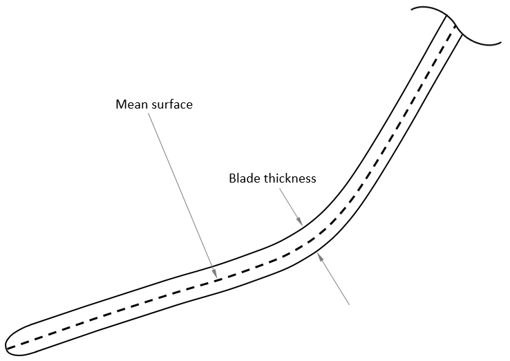
Tangential
This method is operating point-wise by adding the thickness values in tangential direction and is therefore the most independent method.
None
No coupling between suction side and pressure side
Symmetric
Symmetric thickness distribution: control points on suction and pressure side are coupled
Constant distance
Shifting the thickness distribution to pressure/suction side whereas the distribution itself remains constant
Shifting control points in horizontal direction
Global number of control points
All profiles have the same thickness distribution
Adjusts the morhping of hub/shroud-thickness for inner profiles. Default is linear.
Provides adjustments of asymmetry at leading / trailing edge relative to first inner control points respectively.
Problem |
Possible solutions |
|---|---|
Pressure and suction side (...) are intersecting or swapped. |
|
The blade sides are intersecting or they are on the opposite position. Normally this can occur only when loading profiles from file. |
Check the imported profile data if |
Profile of Main/ Splitter blade exceeds its valid range. |
|
Profile is defined for a relative blade length smaller 0% or greater 100%. |
Check the imported profile data or correct the Beziér control points to lie between 0% and 100%. |
Loaded profiles do not correspond to settings of design mode |
|
Profile properties defined by context menu in the design dialog do not match Design mode settings. |
May occur if thickness distribution is loaded from profile manager: a) Check and adjust state of check box LE rounded and TE rounded b) Apply profiles to both hub and shroud resp., or choose identical profiles |
Blade thickness values don't match target thickness on LE/TE. |
|
Current profile thickness on leading- / trailing edge deviate from the specifications of the Blade properties dialog. |
Check the imported profile data if the values for leading and trailing edge match those of the Blade properties dialog. |
Pressure/Suction side at Hub/Shroud: |
|
The combination of of high blade thickness and high meanline curvature results in degenerated blade profiles and prevents creating smooth blade surface. |
Either blade thickness at the specified profile side or meanline curvature at the specified span position has to be reduced . |
|
|
Internal blade thickness is lower than specified in Blade properties dialog. |
|
After changing the blade thickness on leading or trailing edge in the Blade properties dialog, the thickness of the blade at the inner control points is unaffected. It could happen that the thickness on leading and trailing edge is higher than in the middle of the blade. |
Adjust the inner control points |