|
<< Click to Display Table of Contents >> Additional views |
  
|
|
<< Click to Display Table of Contents >> Additional views |
|
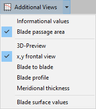
The following information can be displayed in the blade profile dialog using the "Additional views" button: |
|
The Info panel represents information of the designed blade profile:
Throat area
Smallest cross section between 2 neighboring blades
Throat distance spanwise
Throat distance: smallest distance between 2 neighboring blades at every span
LE Throat distance: smallest distance between 2 neighboring blades at every span at leading edge
TE Throat distance: smallest distance between 2 neighboring blades at every span at trailing edge
Actual thickness
Actual orthogonal blade thickness values of hub and shroud profiles at leading edge, at trailing edge, after 1/3 and after 2/3 of the blade length
If the cells are colored red, then the thickness on leading/trailing edge is differing from the Target thickness.
Target thickness
Orthogonal blade thickness values for hub and shroud profiles at leading edge and at trailing edge as defined in the Blade properties dialog.
Please note that the blade thickness on leading and trailing edge should be modified in the Blade properties dialog only. In this case the blade angle calculation should be updated due to the blade blockage.3D-Preview
|
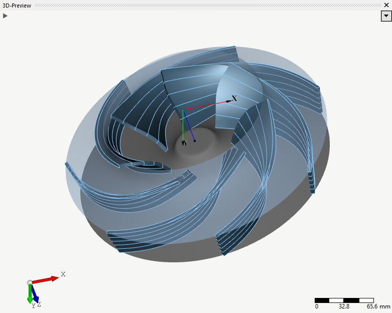
3D model of the currently designed blades as well as surfaces of hub and shroud and mean surfaces. |
|
Furthermore, the smallest cross section between 2 neighboring profiles is displayed. |
Area that is approximately perpendicularly flown through and formed by hub, shroud and two neighboring blades.
Two neighboring blades in m-t-co-ordinates. In the display options ![]() the appearance of the following features can be toggled on/off:
the appearance of the following features can be toggled on/off:
•hub and shroud profiles,
•hub and shroud meanlines,
•throat distance: shortest distance between the blades at hub and shroud,
•LE&TE throat distance: shortest distance between the blades at leading and trailing edge of hub and shroud.
Distance of two neighboring blades in m-t-co-ordinates. For axial machines with a coaxial meridian this gives a good impression of the de facto distance distribution.
See blade surface values.
Undistorted profiles in relative or absolute co-ordinates. In display options ![]() the span to be displayed can be selected.
the span to be displayed can be selected.
Thickness of blade in z-r-co-ordinates. In display options ![]() the definition of thickness can be switched.
the definition of thickness can be switched.