|
<< Click to Display Table of Contents >> Blade edges |
  
|
|
<< Click to Display Table of Contents >> Blade edges |
|
► IMPELLER | Blade edge ![]()
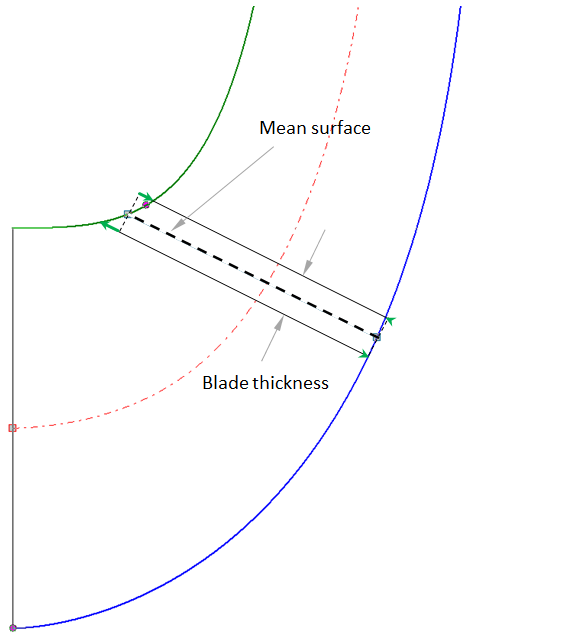
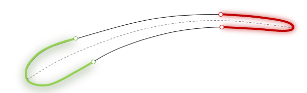
The previously designed blade has a blunt leading and trailing edge (connection line between endpoints of suction and pressure side).
The blade edges are designed by specifying its thickness distribution. The representation of the blade thickness s is made on 15% of the straight blade length l on leading and trailing edge.
If the complete thickness distribution including leading or trailing edge was already designed in the Blade profile dialog, then the Edge position (transition from blade edge to blade suction/pressure side) has to be defined only.
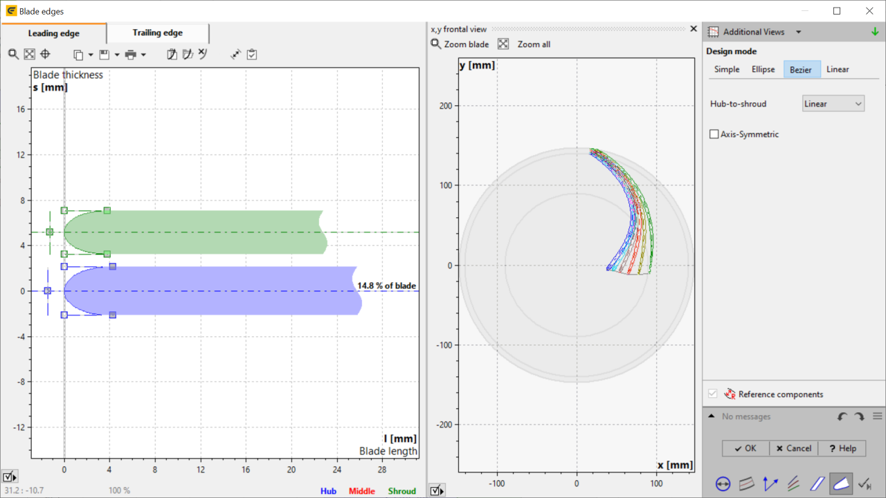
There are two different options to design the edge shape from hub to shroud/ tip (except for the "Simple" design mode):
▪Linear
Blade edges at hub and shroud/ tip can be designed independently, while the intermediate spans are interpolated linearly.
▪Uniform
Only the edges at hub can be designed. All spans use identical parameters.
In panel Design mode the blade edge shape can be selected:
The blade edge has a blunt end. A straight line is calculated from the endpoint of suction side perpendicular to the mean line.
Cutoff on meridional leading/trailing edge effects cutting the blade on the corresponding meridional surface.
The blade thickness is changing linear, with an elliptic rounding at the end.
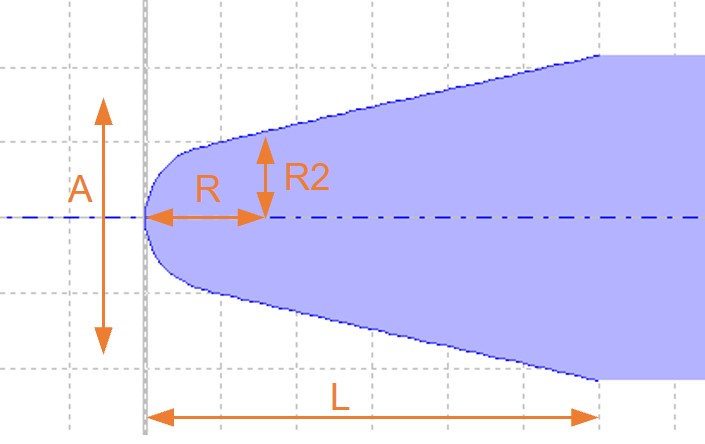
The edge is defined by the overall length L, the radius of the end rounding R and the axis ratio R/R2 of the end rounding.
Furthermore an asymmetry A can be specified.
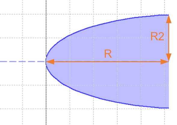
The blade edge is rounded elliptically.
The axis ratio R/R2 can be defined. One axis runs on the mean line, the other perpendicular.
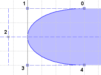
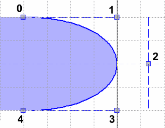
For this purpose 4th order Bezier curves are used.
Points 0 and 4 representing the transition between the blade sides and the rounded blade edge. You can move these points only along the corresponding blade side. Bezier points 1 and 3 can only be moved on straight lines which correspond to the gradient of the curve in points 0 or 4, respectively in order to guarantee smooth transition from the contour to the blade edge. Bezier point 2 is not restricted to move - it has the most influence to the shape of the blade edge. Its horizontal position is calculated automatically in such way that the leading edge starts at position l=0 and the trailing edge ends at position l=blade length. The blade edges are designed at the first or last 10% of the blade length.
Axis-Symmetric results in symmetric geometry, i.e. points 0/4 and 1/3 have the same horizontal position and point 2 is on the middle line.
Problem |
Possible solutions |
|---|---|
Blades exceed meridional boundaries due to specified blade edge geometry. |
|
The warning indicates that some parts of the blade leading edge are outside the meridional dimensions of the component.
The orthogonal application of thickness on the mean lines can result in some blade position outside the meridional boundaries. Therefore, the model finishing option 'solid trimming' will not be available. |
Dependent upon the location of these areas one has to modify leading or trailing edge. If the leading edge (or the trailing edge of turbines) exceeds the meridional boundaries you can adjust it in the Meridional contour dialog only. Exceeding trailing edge (or leading edge of turbines) can be corrected by trim on in/outlet. |
It is impossible to trim blade at leading/trailing edge. |
|
The resulting blade has to be trimmed on the meridional leading and trailing edge. In special situations this trim operation is not possible for geometric reasons. |
Meridional contour, Mean line: Blade profile: Reduce blade thickness. |
|
|
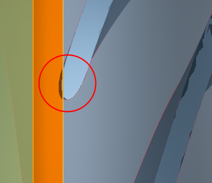
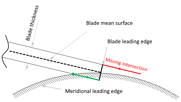
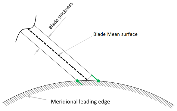
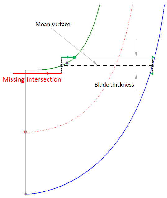
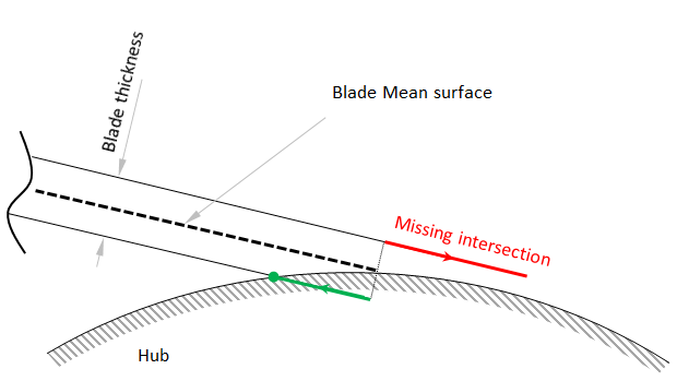
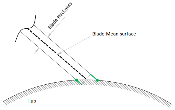
Error when extrapolating Blade to reach Hub/Shroud surface. |
|
The orthogonal blade thickness is added to the blade mean line to create the blade sides. Then one blade side will be trimmed on hub/ shroud, the other one will be extrapolated to hub/ shroud surface. For the below illustrated configurations of meridional contour and blade geometry the extrapolation fails. |
Meridional contour: Account for blade thickness during leading edge positioning or align leading edge towards the direction of the shroud normal (see images below). The trimming/ extrapolation of blade and hub/ shroud will be successful depending on blade angles and blade thickness. A solution can be the modification of the leading edge by repositioning and changing its angle relative to the shroud. Blade properties: Increase the number of spans. Blade profile: Reduce blade thickness or change thickness definition to "Perpendicular to mean line". Mean line: Check mean line shape and keep lean angle on a low level. |
|
|
|
|
Distance between blade and hub is higher than the critical value. |
|
The ratio (distance from blade to hub) / (average diameter) is higher than the critical value. This could result in trimming issues later on. |
Try to make lean-angle smaller and/ or decrease thickness. |
Impossible blade edge design: overlapping leading and trailing edge blade. |
|
Overlapping of Leading and trailing edge, impossible to design pressure and suction side. |
Reduce the edge positions of one or both edges. |
|
|