|
<< Click to Display Table of Contents >> Model finishing |
  
|
|
<< Click to Display Table of Contents >> Model finishing |
|
► IMPELLER | Model finishing ![]()
Model finishing is used for geometry post-processing of the 3D-geometry created in prior design steps:
Blade fillets |
Fillet creation at join of blade and hub/shroud. |
[Impellers, Stators] |
Extended blade |
Extended blade solid geometry. |
[Impellers, Stators] |
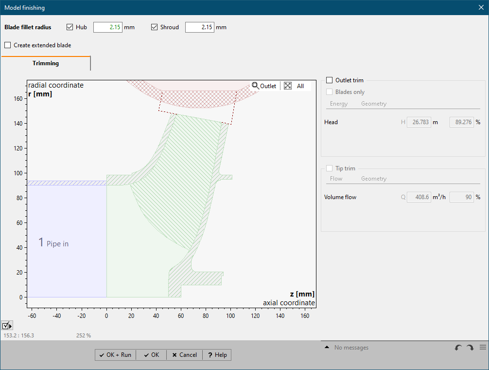
Trimming |
Trimming of impeller geometry. |
[Impellers] |
Blade fillets
|
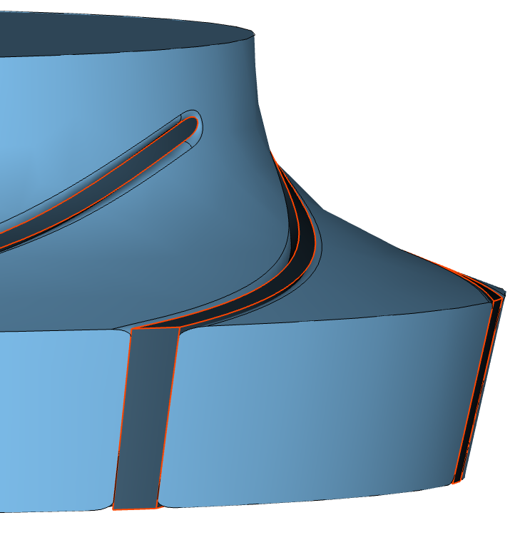
The edges between blade and hub/shroud can be rounded. The fillet affects only the solid geometry of Flow domain and Material domain. The fillet radius should not be larger than the recommended value. Limitations
|
||||
|
•Flow domain, Flow domain (virtual) •Material domain •Blade  Flow domain
 Material domain |
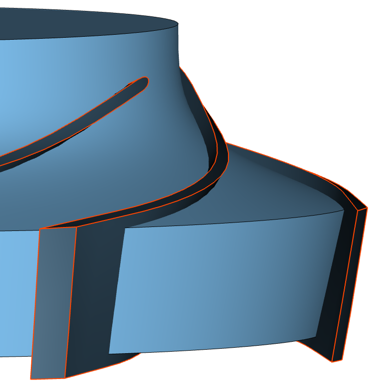
Solid geometry is created by sewing and intersecting initial surfaces. Related operations can be time-consuming depending on the hardware processing power. Details: •Extension geometry is integrated into the component's Flow domain (virtual) solid geometry •RSI connection geometry is integrated into the related adjacent component's Flow domain (virtual) solid geometry •hub and shroud material geometry is sewed with blade geometry resulting in Material domain solid geometry •Blade projection geometry is intersected with Flow domain solid geometry As a result, the Flow domain and optional Material domain are created for both, 360° model (Full 360°) and a rotational symmetric segment around a single blade (Segment). Solid geometry is not available in point-based exports.
|
||||
|
|
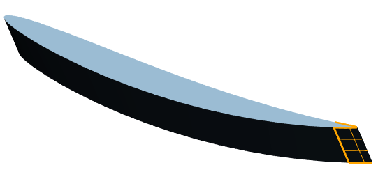
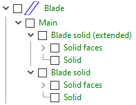
The solid geometry of the blades extended through hub and shroud is created during the finishing process. Additionally, blade is extended through leading/trailing edge, if it is fixed as well as trimmed at inlet/outlet. It can be used for custom intersection in an external CAD-system. The "Blade solid (extended)" is part of the 3D model tree and can be exported by right-click.
|
•<OK> |
The configuration is saved in the project, but the 3D-model is not updated. |
•<OK + Run> |
The configuration is saved in the project and the 3D-model is updated using the model finishing options. |
The model finishing can be executed globally for all vaned components by PROJECT/ Model finishing.
Problem |
Possible solutions |
|---|---|
Solid generation is not available. Blades exceed the meridional boundaries. |
|
Blade geometry is outside the primary meridional path. Solid geometry for flow domain and material domain is not supported in this configuration. |
Change position or shape of related blade edge (link). |
Solid generation is not available. Both blade edges are fixed at inlet/outlet. |
|
Blade edges at both inlet and outlet would divide flow domain geometry into multiple solid bodies, which is not supported. |
Change position of either leading edge or trailing edge (link). |
Solid generation may fail due to meridional contour. |
|
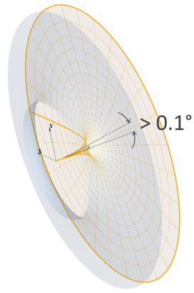
Segment: Generation of segment may fail due to meridional contour. |
|
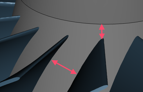
The angle between rotation axis and hub contour is too small (lower than 0.1 degree).
|
Set a value for hub diameter higher than zero or round the hub contour to avoid a geometry with needle form. |
Solid generation may fail due to tangential difference between hub and shroud at leading/trailing edge, or low number of spans. |
|
Very low number of spans |
Increase the number of spans up to at least 4 |
Fillets not supported. |
|
Fillets are not supported if generation of solid geometry is not possible. |
- |
Fillets creation on shroud deactivated. |
|
Fillets on shroud are not supported for unshrouded designs. |
- |
Curvature of Leading edge/Trailing edge/Blade edges at Hub/Shroud could be too large for fillet creation. |
|
Sharp Blade edges could prohibit fillet creation between blade and hub/shroud and could cause long computation time respectively. |
Less sharp design of blade edges or reduction/deactivation of fillet radius. |
3D-Error: Finishing failed! |
|
Inlet (nearly) tangential to hub or shroud |
Change Meridional contour: Avoid tangentiality |
3D-Error: Finishing failed! (Could not extend blade) |
|
Extending the blade to a scaled Hub/ Shroud surface failed. |
See solution of Error while extrapolating Blade to reach Hub/ Shroud surface |
3D-Error: Finishing failed! (Could not intersect solids of Blades and Flow domain) |
|
Intersecting a single blade with Flow domain failed. |
Try using a different number of data points |
3D-Error: Finishing failed! (Could not create fillet) |
|
Fillet creation at blade root failed (see limitations). |
Decrease fillet radius |
3D-Error: Finishing failed! (Creating trimmed segment) |
|
Cutting a segment from Flow domain failed. This can occur due to heavy bendings of hub or shroud. |
Reduce bending at high curvature regions of hub- or shroud-contours. |
3D-Error: Finishing failed! (Fusing solids) |
|
Fusing of real geometry with CFD setup components (Extension or RSI connection) failed. |
Increase the number of spans |
3D-Error: Finishing failed! (Creating new Flow domain from segment) |
|
Creating a new Flow domain from Segment failed. |
Decrease blade fillet radius. |
3D-Error: Finishing failed! (Creating Material domain from Flow domain) |
|
Creating a Material domain failed. |
Deactivate hub and shroud materials |
3D-Error: Blade projection to RSI failed! |
|
Projection of blade to RSI (Extension) failed. |
Change CFD setup: Modify Extension or remove Blade projection |
3D-Error: Blade tip projection to casing failed! |
|
Projection of blade to casing (shroud) failed. |
Change CFD setup: Remove Blade projection or RSI connection |