|
<< Click to Display Table of Contents >> Trimming |
  
|
|
<< Click to Display Table of Contents >> Trimming |
|
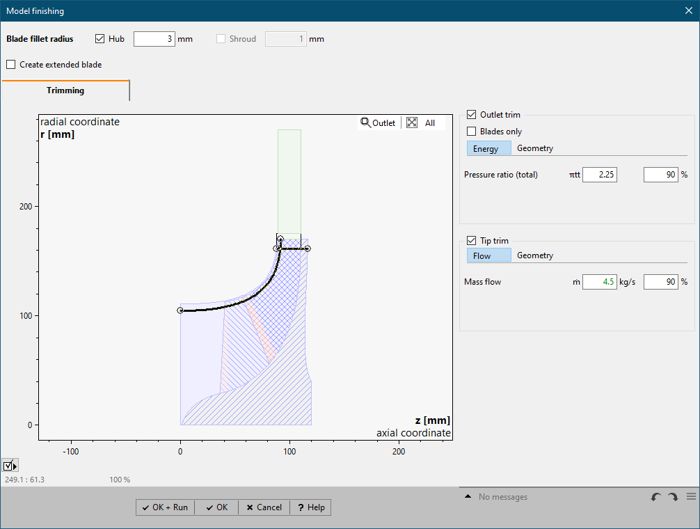
Trimming can be used to derive adjacent impeller designs in order to reduce the energy transmission and/ or flow rate of an already existing impeller.
The following options are available:
Trim operation |
Trimming impeller |
Application |
Inlet trim |
at inlet |
Radial inflow turbines only |
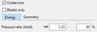
Outlet trim |
at outlet |
Axial and centrifugal impellers except radial inflow turbines |
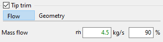
Tip trim |
at blade tip |
Unshrouded impellers only |
The geometry of the trim curve can be defined based on the following criteria:
Energy |
Straight line resulting from •absolute energy or •relative energy related to Global setup definition
The reduced impeller diameter d2* can be calculated by , where * is related to the reduced numbers. The ratio d2*/d2 should not be lower than 0.8 ... 0.85. |
Inlet/Outlet trim for radial impellers only |
Flow |
Offset curve of blade tip resulting from •absolute flow or •relative flow related to Global setup definition
The reduced impeller width b* can be calculated by , where * is related to the reduced numbers. |
Tip trim only |
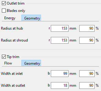
Geometry |
Trim curve resulting from •absolute axial/radial values at hub/shroud for Inlet/Outlet trim •absolute width at inlet/outlet for Tip trim •relative values related to the untrimmed geometry
|
Always available |
When activating the option Blades only for Inlet/Outlet trimming the meridional path (incl. material solids) is not trimmed.
In case of trimming the meridional path virtual geometries are updated accordingly:
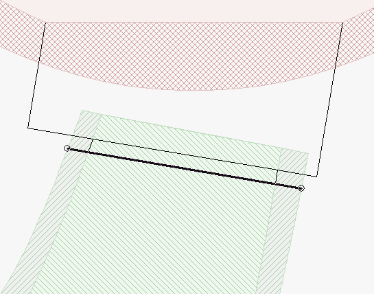
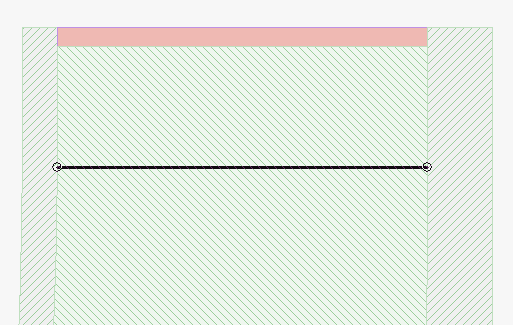
Areas in the meridional path where a trim curve cannot be positioned due to internal restrictions are marked in red:
Problem |
Possible solutions |
|---|---|
Trimming through blade edge not supported. |
|
Trim curve intersects the Leading/Trailing edge. |
Change position of the trim curve ensuring no intersection with any blade edge. |
Main blade is trimmed, but Splitter blade is not. Splitter blade is trimmed, but Main blade is not. |
|
Trim curve does not cut both, main and splitter blade. |
Change position of the trim curve ensuring both main and splitter blades are cut by trim curve. |
Trim curve is not located inside blade region. |
|
Option "Blades only" is activated, but trim curve does not cut any blade. |
Change position of the trim curve ensuring blades are cut by trim curve. Alternatively, deactivate option "Blades only". |
Cutting off both blade edges at interfaces is not supported. |
|
Trimming would produce impeller geometry with both Leading and Trailing edge cut off at inlet/outlet, which is not supported. |
Change position of the trim curve ensuring blades are not cut by trim curve. Move blade edge not being cut by the trim curve away from meridional interface. Alternatively, activate option "Blades only". |