|
<< Click to Display Table of Contents >> Blade surface values |
  
|
|
<< Click to Display Table of Contents >> Blade surface values |
|

Stream lines must be known a-priori (see Meridional flow calculation). If the meridional flow calculation failed, the blade surface values cannot be calculated and the diagram will not be available. Stream lines rotated around z-axis build stream surfaces.The relative velocities will be calculate in a blade-to-blade section, that is encapsulated by two adjacent stream surfaces. Single values of relative velocities will be determined at r = constant. Before that an average velocity is calculated on the basis of the continuity equation:
![]()
The part mass flow is a function of the entire mass flow, number of blades and number of stream lines. Between two adjacent stream surfaces there is always the same mass flow.
The cross section is determined by stream line distance Δh, the radius r, the tangential distance between pressure and suction side of two neighboring blades Δt and by a mean relative flow angle:
![]()
In the picture above a section according to the following equation is displayed:
![]()
With the assumption of zero circulation of the absolute flow within a stream surface (green surface) the relative velocity at the suction side can be calculated by:
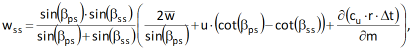
here u is the local circumferential velocity, cu is the circumferential component of the absolute velocity, βss and βps are the blade angles at suction and pressure side respectively. Due to the fact that mean relative velocity is an averaged value of wss and wps, the relative velocity at the pressure side can be calculated with:
![]()
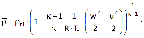
The continuity equation has to be solved iteratively for the relative velocity since the density of a compressible medium is determined by the relative velocity. The density can be calculated from isentropic relation:
The average relative flow angle is approximated by the average value of the blade angle at suction- and pressure side. At a certain radius the assumption applies that due to the slip (decreased power) the flow cannot be considered as blade congruent anymore. The mean relative flow angle will be corrected by the slip at loci with a radius bigger than this Stanitz-Radius.
The whole procedure is based on the assumption that the flow is considered as frictionless and that shocks as well as heat transport across boundaries do not occur. There might by geometric constellations where the cross section (blue surface in the images above) is too small for the mass flow specified in the global setup. If this happens the equation can't be solved for the average density and relative velocity and no data is displayed for the respective span.
Static pressures at suction and pressure side can be determined by the velocities. To this end a relation between the enthalpy difference between suction and pressure side and the meridional derivative of the swirl is used:
![]()
The blade loading can be expressed in terms of the pressure difference between suction and pressure side and divided by the total inlet pressure:
![]()
For incompressible fluids the second therm within the brackets is zero.
Another formulation of the blade loading makes use of the velocity difference between suction and pressure side and divided by the average velocity:
![]()
Beyond the afore mentioned variables the average circumferential component of the absolute velocity cu as well as the average swirl B can also be displayed. Those quantities are determined by:
![]()
![]()
Also the Ackeret criteria are displayed together with the relative velocities. In accordance to the below defined Ackeret criteria the maximum relative velocity of the respective span shall not be bigger than 1.8·w2, whereas the minimum relative velocity shall not be smaller than 0.3·w1 (w1 and w2 are the average relative velocities at LE and TE resp.). Those limits (max. and min. velocities) are not displayed for splitter blades.
![]()
![]()
![]()
[ Compressors and Turbine rotors only ]
Mach Number can be displayed both relative as well as absolute.
![]()
![]()
Here a is the sonic speed defined by:
![]()
The specified mass flow can only be realized for a certain size of the cross section at the given total inlet state. A critical cross section is determined by the following set of equations under assumption of perfect gas behavior:
![]()
![]()
![]()
![]()
![]()
Here πcr is the pressure ratio at which the flow is at sonic speed in the smallest cross section:
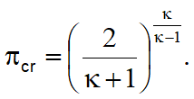
For Air πcr = 0.528. At the given inlet total state it is not possible to transport the mass flow through a cross section smaller than Acr. Both the actual (A) and the critical cross section (Acr) can be displayed. The actual cross section is the cross section according to the blue surface in the picture above.
If the combination of mass flow, total inlet condition and geometry (cross section) yields a state that is physically not possible a solution cannot be determined and a hint is displayed saying: "No solution due to shocks or transsonic behavior at span: x". x will hold all spans for which the hint is true.