|
<< Click to Display Table of Contents >> CFD, FEA |
  
|
|
<< Click to Display Table of Contents >> CFD, FEA |
  
|
► PROJECT | Export | CFD, FEA ![]()
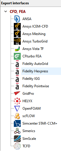
The CFD, FEA group contains the supported CFD and FEA product interfaces.

The next table display a summary of the most important information related to all supported export interfaces.
[ I = Impeller S = Stator V = Volute MC = Multi-Component export supported ]
Menu entry |
Description |
Component type |
|||
ANSA |
*.igs |
I |
S |
V |
MC |
•File | Open •Select *.igs file |
|
|
|
|
|
*.stp; *.x_t; *.x_b |
|
|
|
|
|
Ansys Workbench: •Add "Mesh" container to "Project Schematic" •Right click on "Geometry" inside the "Mesh" container: |
|
|
|
|
|
*.geomTurbo |
I |
S |
V |
MC |
|
•File | New Project •“Initialize a New Project from a geomTurbo File” •Select *.geomTurbo file |
|
|
|
|
|
Fidelity Hexpress |
*.stp |
I |
S |
V |
MC |
File contains designed geometry as volume. |
|
|
|
|
|
*.tinXML, *.stp |
I |
S |
V |
MC |
|
A STEP file with named geometries is created. The names are visible in ICEM-CFD if the file is imported via Workbench Reader. Parameters are saved in a separate XML file. |
|
|
|
|
|
Fidelity IGG |
*.dat |
I |
S |
V |
MC |
Multiple data files are generated: section.dat, diffusor.dat, curves.dat •File | Import | IGG Data •Select *.dat file •Repeat steps for remaining files |
|
|
|
|
|
Fidelity Pointwise |
*.step |
I |
S |
V |
MC |
•File | Import | Database •Select *.step file |
|
|
|
|
|
*.spro, *.stl |
I |
S |
V |
MC |
|
The *.spro file contains all project information. The *.stl files contain the geometry in STL format as triangulated surfaces. In SimericsMP/ SimericsMP+: Select *.spro file under File | Open |
|
|
|
|
|
Simcenter STAR-CCM+ |
*.stp |
I |
S |
V |
MC |
•File | Import | Import Surface Mesh... •Select *.stp file |
|
|
|
|
|
*.tse or *.inf, *.curve |
I |
S |
V |
MC |
|
2 alternative formats are available: a) Session file *.tse (not available within Ansys Workbench) 4 files are created: a session file <filename>.tse and Load the session file <filename>.tse under Session | Play Session. b) Initialization file *.inf 4 files are created: a initialization file <filename>.inf and Load the initialization file <filename>.inf under File | Load TurboGrid Init File. Alternatively you can open the curve files (<filename>_hub.curve, <filename>_shroud.curve, <filename>_profile.curve) manually under File | Load Profile Points. Beside the selection of the *.curve files one has to specify the number of blades, define the z axis as rotational axis, select the cartesian coordinate system and the length unit specified in CFturbo for export |
|
|
|
|
|
*.tcfd, *.stl |
I |
S |
V |
MC |
|
The *.tcfd file contains all the CFD project information. The *.stl files contain the geometry in STL format as triangulated 3D surfaces. The .tcfd file is read and the simulation is performed automatically. In TCFD run command: More info at CFD support website |
|
|
|
|
|
Ansys Vista TF |
*.fil, *.con, *.geo, *.aer, *.cor |
I |
S |
V |
MC |
5 files are created: - default file <filename>.fil Run compiled executable version of the Vista TF code. Exported files need to be in the same folder than the executable file. |
|
|
|
|
|
GridPro |
*.stp; *.stl |
I |
S |
V |
MC |
File contains designed geometry as volume model. |
|
|
|
|
|
SimScale |
*ssc, *.step |
I |
S |
V |
MC |
The *.ssc file contains all project information. The geometry is exported in *.step format. The case can be transferred to SimScale and run automatically from CFturbo if desired. |
|
|
|
|
|
Helyx |
*.stl |
I |
S |
V |
MC |
The *.stl files contain the geometry in STL format as triangulated 3D surfaces. |
|
|
|
|
|
scFLOW |
*.step |
I |
S |
V |
MC |
The *.step files contain the geometry in STEP format. |
|
|
|
|
|
CFturbo FEA |
*.cftfea, *.step |
I |
S |
V |
MC |
The *.cftfea file contains the project information needed to load the case in CFturbo FEA. The *.step files contain the geometry in STEP format. |
|
|
|
|
|
Problem |
Possible solutions |
|---|---|
Flow inlet does not match previous outlet. |
|
|
If possible, activate the RSI connection in CFD setup of the impeller. |
|
Inlet geometry was defined in such a way that it does not match the inlet of the previous component. See geometric coupling for more details. |
Flow outlet does not match next inlet. |
|
|
Outlet geometry was defined in such a way that it does not match the outlet of the next component. See geometric coupling for more details. |