|
<< Click to Display Table of Contents >> Simerics |
  
|
|
<< Click to Display Table of Contents >> Simerics |
|
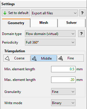
In addition to the STL settings, the user can select which files should be exported.
Export all files: Configuration file (*.spro) and STL files are exported.
Export configuration file only: STL files are not exported. This option can be useful for saving export time if the user wants to generate a new configuration file with different settings (e.g. mesh parameters, rotational speed, boundary condition values, fluid data etc.). In this case, all geometrical export requirements (like solid trimming) are disabled in the CFturbo Export window.
Export STL files only: The configuration file is not exported. This option is useful, e.g. if STL files for some (but not all) components have to be exported again due to an unsatisfactory triangulation. In this case, the original configuration file, which refers to all components, should not be overwritten.
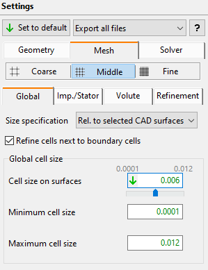
Mesh settings are specified globally for all selected CFturbo components to be exported.
The following global mesh parameters are available:
•Min. cell size
•Max. cell size
•Cell size on surfaces
If the user wants to set specific parameters for predefined regions, the option “Use local cell size on surfaces” must be activated.
If not, the global value “Cell size on surfaces” is used for all regions. Specific mesh parameters can be set for the following regions:
Rotational symmetric components |
|
Region |
Description |
Hub |
- |
Shroud |
- |
Blade sides |
Blades suction and pressure sides |
Blades LE / TE / Tip |
Blades edges leading, trailing and tip |
Secondary flow path hub |
Hub material domain surfaces |
Secondary flow path shroud |
Shroud material domain surfaces |
Inlet |
- |
Outlet |
- |
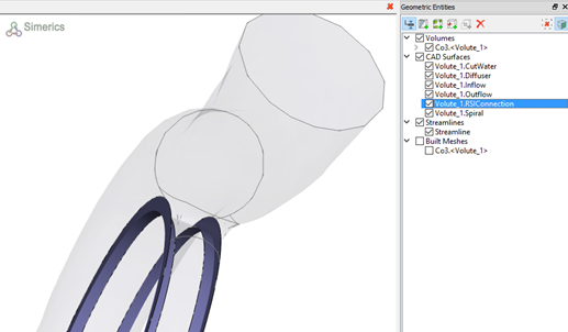
For RSI-Connection surfaces, the “Hub” parameters are used for meshing:
Secondary flow path mesh parameters are useful if a fine meshing is necessary in gap zones between solid bodies and casing.
Enabling the option "Refine casing", local cell sizes set for hub and shroud are also used for the casing surfaces.
Volutes |
|
Region |
Description |
Spiral |
- |
Diffuser |
- |
Cut-water |
- |
Splitter |
Volute splitter (double volutes) |
Inlet |
- |
Outlet |
- |
For RSI-Connection surfaces, the “Spiral” parameters are used for meshing:
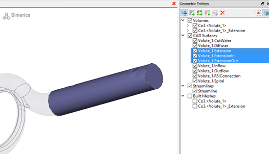
In case the volute extension is exported, “Diffuser” mesh parameters are used for the extension walls.
“Inlet” and “Outlet” mesh parameters are used for the extension inlet and outlet:
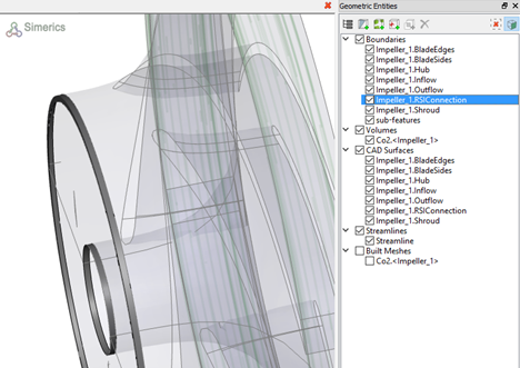
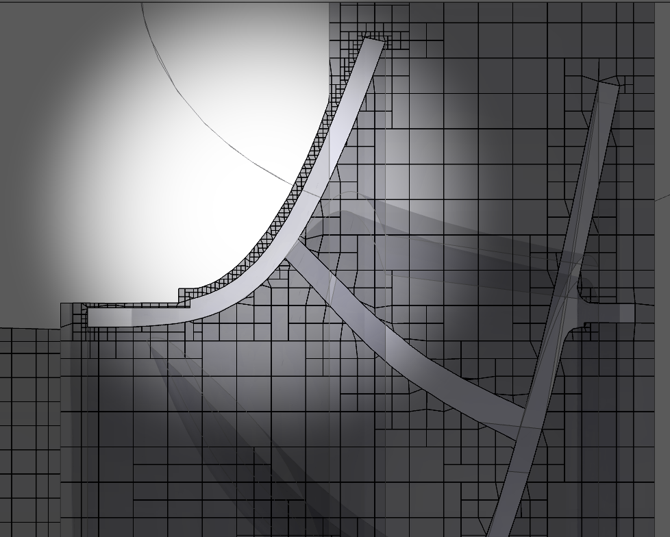
In some cases mesh refinement zones are more effective than applying local mesh sizes. This might be true e.g. for secondary flow path simulations where very small gaps have to be meshed. The images below show a typical case:

Mesh resulting from setting local mesh parameters on hub and shroud as well as casing surfaces

Mesh resulting from using refinement zones in isolated regions
The use of refinement zones allows for high quality refinement in regions with small gaps, avoiding high numbers of cells. Refinement zones can be applied within the whole geometry and can be set by defining the refinement cell size and cylindrical refinement area:
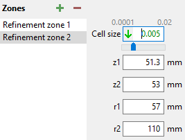
The following parameters are available:
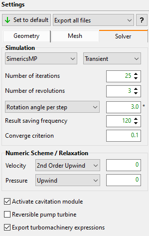
•Solver selection (SimericsMP or SimericsMP+)
•Selection of simulation type: Steady or transient
•Number of iterations
•Result saving frequency (only for transient simulations)
For transient simulations, two special parameters are available. These parameters differ from the Simerics original ones, but are more comfortable for turbomachinery:
•Number of revolutions: number of impeller rotations to be simulated. The original Simerics parameter “Simulation Time (Duration)” is calculated using this new parameter and the rotational speed of the impeller. Default value is 3 revolutions.
•Rotation angle per step: number of degrees the mesh is rotated by per step. The original Simerics parameter “Number of time steps” is calculated using this new parameter and the number of revolutions to be simulated. Default value is 3 degrees.
•A global value for converge criterion can be set. This value is used for all active modules. In case the default Simerics value (0.001 for steady simulations and 0.1 for transient simulations) is used, values are not written in the SPRO-file allowing Simerics to change the values automatically if the user switches interactively in the Simerics-GUI between steady and transient simulation.
•Numeric scheme and Relaxation values
•Cavitation (activated by default for pumps). Not available for compressible flow (compressors, gas turbines, fans)
•Reversible pump turbine: enabling this option, adapted boundary conditions are used to simulate the pump as a turbine.
•Turbomachinery expressions are useful to check the simulation convergence.
IMPORTANT: Plotting of user defined expressions is not supported for Simerics versions lower than 4.2.8 and can cause problems in these versions.
The character "_" is not allowed for component names for the time being.