|
<< Click to Display Table of Contents >> Meridian |
  
|
|
<< Click to Display Table of Contents >> Meridian |
|
This view consists mainly of a diagram containing the meridional shape of all components.
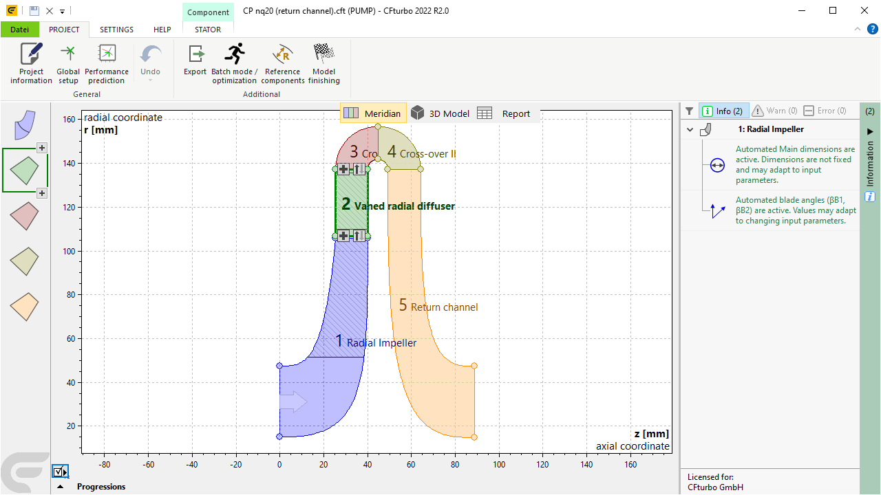
Active components are displayed with their respective color, inactive components are displayed grey.
The diagram depicts the assembled meridional shapes of the project components and their connecting interfaces
A large arrow on the inlet of the first component illustrate the flow direction.
Captions showing component name and a consecutive number are displayed as well.
The currently selected component is displayed with thick border and can be changed by mouse click on a component.
|
Component toolbarIf the mouse moves over the selected component the components menu is shown in compact style. Alternatively you can use the corresponding ribbon menu (see IMPELLER/ STATOR/ VOLUTE).
Component context menu Right clicking on the component opens its context menu, see Activate/ Rename/ Delete components. |
|
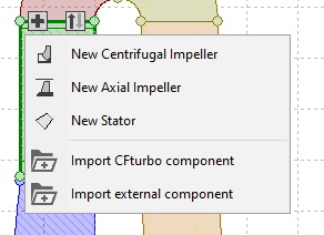
Adding ComponentsVia the See Add component.
|
|
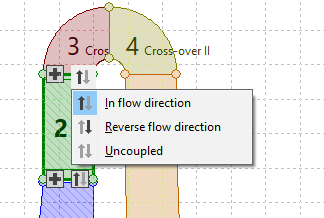
Geometric couplingThe direction of the geometric coupling between components is displayed by small symbols (see left). |
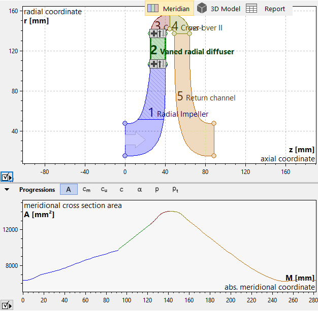
Below the meridional view, progressions of several physical quantities along the flow direction of all components can be displayed:
A |
Cross section area |
cm |
Meridional velocity |
cu |
Circumferential velocity |
c |
Absolute velocity |
α |
Flow angle |