|
<< Click to Display Table of Contents >> t, m Conformal mapping |
  
|
|
<< Click to Display Table of Contents >> t, m Conformal mapping |
|
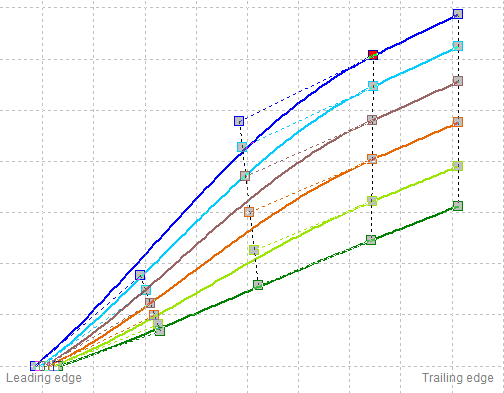
The blade is designed in the conformal t, m mapping by Bezier curves.
|
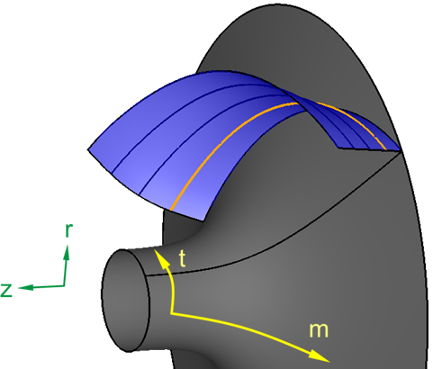
The spatially curved meridional flow surfaces are mapped to a plane by coordinate transformation. This coordinate system has the angle in circumferential direction t as abscissa and the dimensionless meridional extension m as the ordinate. Both quantities are created by the reference of absolute distances in meridional (M) and tangential direction (T) to the local radius r:
|
By default the mean lines are represented by 3rd order Bezier curves (4 control points):
•2 points define the endpoints at leading edge (left) and trailing edge (right).
These points can be moved horizontally only, because their meridional position m is already fixed.
CFturbo's primary design is fixing the leading edge point for all cross sections at tangential coordinate t=0 and meridional coordinate m=0, while the trailing edge point is determined by the meridional extension Δm (defined in the Meridional contour design step) and the wrap angle Δφ. The initial wrap angle Δφ is based on empirical functions.
•2 inner points define the inner shape of the meanline.
These inner points can be moved along the dashed lines only, which represent the blade angles βB1 (leading edge) and βB2 (trailing edge) specified in the Blade properties design step.
If you select any point of the inner (hub) or outer (shroud) cross section, you can rotate the related coupling line between the spans around the opposite end point.
If you select any point of the inner spans, you can move the complete coupling line in horizontal direction.
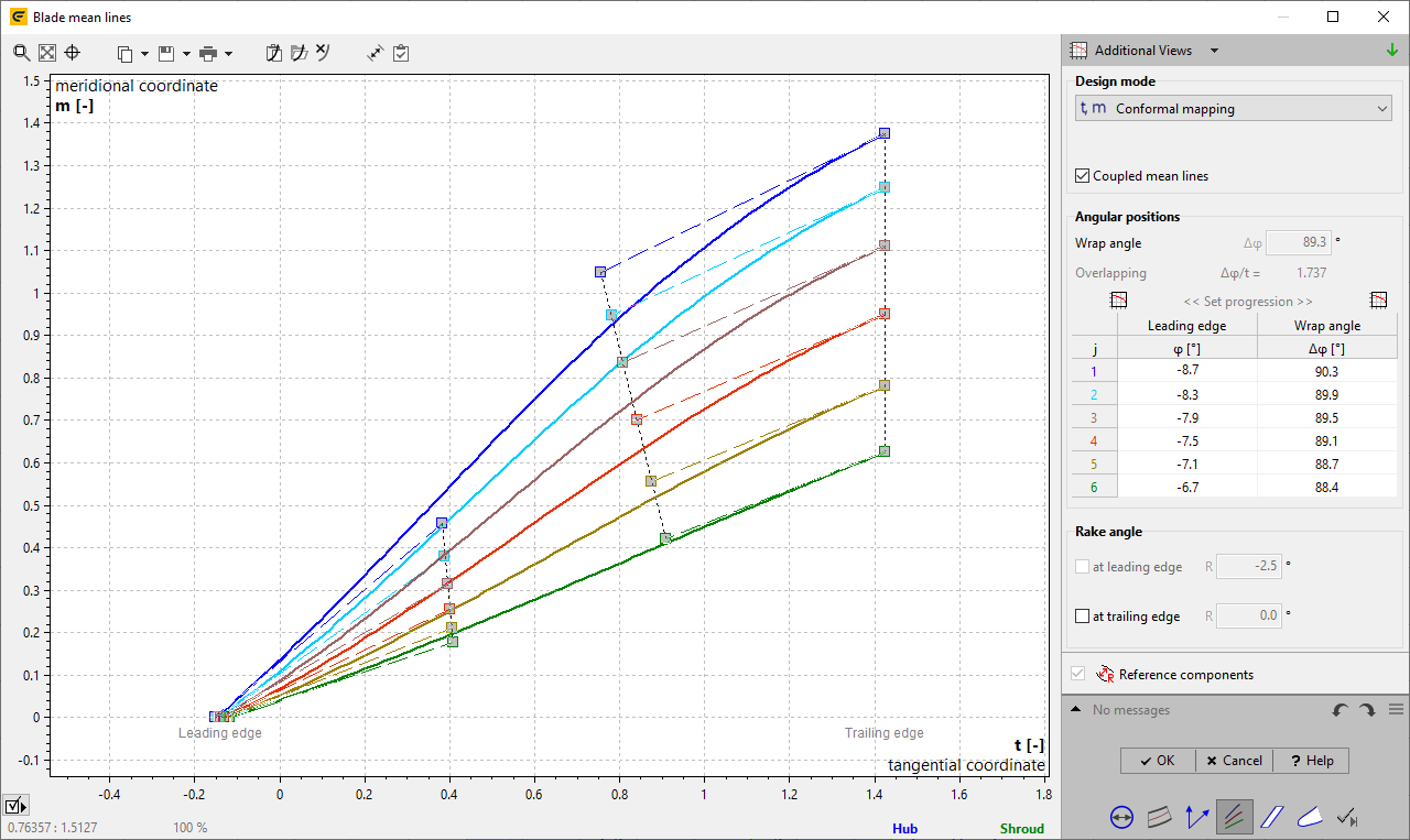
The table Angular positions contains the values of the tangential leading edge position ϕ0 and the wrap angle Δϕ. A distribution of these values along the span positions can be specified using the button above the table.
The context menu of the curves contains additional options:
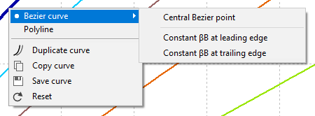
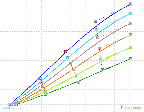
•Bezier curve/ Central Bezier point:
An additional central Bezier point can be activated, which can be moved freely and provides more flexibility.
•Bezier curve/ Constant βB1 (βB2) near leading (trailing) edge:
An additional control point at leading and/ or trailing edge is added, which defines a straight line with constant βB1/ βB2.
The exact position can be defined by the point context window as r, z, or m value.
•Polyline/ Load curve:
After switching the curve mode to polyline, a user-defined polyline can be loaded.
Also, a mean line can be loaded from the profile manager. In this case the dimensionless mean line selected in the profile manager is staggered and scaled with the properties of the reference mean line to be exchanged.
![]() The visibility of the inner mean lines can be toggled via "Inner spans".
The visibility of the inner mean lines can be toggled via "Inner spans".