|
<< Click to Display Table of Contents >> Axial Gas Turbine / Compressor |
  
|
|
<< Click to Display Table of Contents >> Axial Gas Turbine / Compressor |
|
► Rotor | Main dimensions ![]()
The Main Dimensions menu item is used to define main dimensions of the axial rotor. Main Dimensions are forming the most important basis for all following design steps.
|
|
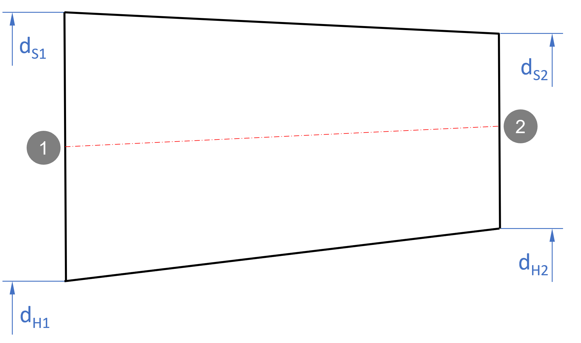
The real flow in the impeller/rotor is turbulent and three-dimensional. Secondary flows, separation and reattachment in boundary layers, transient recirculation areas and other features may occur. Nevertheless it is useful - and it is common practice in the turbine design theory - to simplify the realistic flow applying representative streamlines for the first design approach. Employing 1D-streamline theory the following cross sections are significant in particular: •inlet (index 1) •outlet (index 2) |
Details ¢ Setup |
Problem |
Possible solution |
|---|---|
Inlet boundary conditions do not fit previous component. |
|
If a stator is located prior the impeller or rotor, boundary conditions for the determination of the main dimensions will be calculated on the basis of the thermodynamic state at its outlet. In case of an undefined thermodynamic state at this location the inlet boundary conditions (i.e. total pressure and temperature) will be taken from the global setup. |
Adjust the stator geometry (dimensions or blade angles) or change the Global setup (e.g. decrease mass flow). |