|
<< Click to Display Table of Contents >> Parameters Gas Turbine |
  
|
|
<< Click to Display Table of Contents >> Parameters Gas Turbine |
|
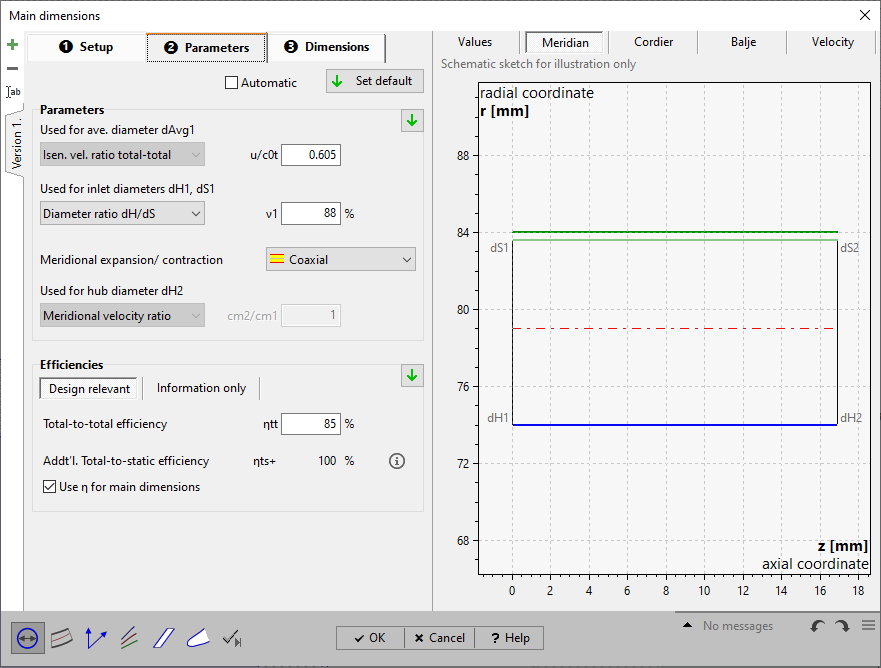
On page Parameters you have to put in or to modify parameters resulting from approximation functions in dependence on specific speed nq or flow rate Q.
See Approximation functions.
For details of how to handle the parameter edit fields please see Edit fields with empirical functions.
|
Parameter and efficiency values can be handled manually or can be switched to automatic update by the checkbox on top of the page. Then the default values are used always, even after design point modifications (see Global setup). |
If the automatic mode is not selected the current default values can be specified by one of the following options:
|
globally by the button on top of the page |
|
regionally by the default button within the Parameters or Efficiency region |
|
individually by the default button within the input field when selected |
The panel Parameters allows defining alternative parameters in each case for the calculation of the following impeller diameters:
|
||||
|
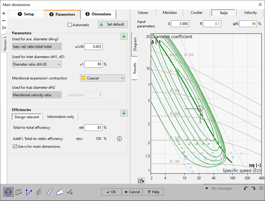
The diameter coefficient is a parameter for the Balje diagram but not a design parameter. With its help suggestions for isentropic velocity ratio total-static νts as well as for the inlet width ratio b1/d1 or the diameter ratio dH/dS can be get (only if total-to-static pressure ratio πts is specified, see global setup).
One of the following parameters has to be specified for the calculation of the mean inlet diameter 0.5(dS1+dH1).
Isentropic velocity ratio total-total νtt= u/ct0 |
u: Peripheral velocity at inlet ct0: spouting velocity
(only if total-to-total pressure ratio πtt is specified, see global setup) |
Isentropic velocity ratio total-static νts= u/c0 |
u: Peripheral velocity at inlet c0: spouting velocity
Defaults by Balje diagram (only if total-to-static pressure ratio πts is specified, see global setup) |
One of the following parameters has to be specified for the calculation of the rotor inlet width b1.
Diameter ratio dH/dS |
Inlet hub diameter dH1
|
Inlet width ratio h/dS1 |
h: inlet width Defaults by Balje diagram (only if total-to-static pressure ratio πts is specified, see global setup) |
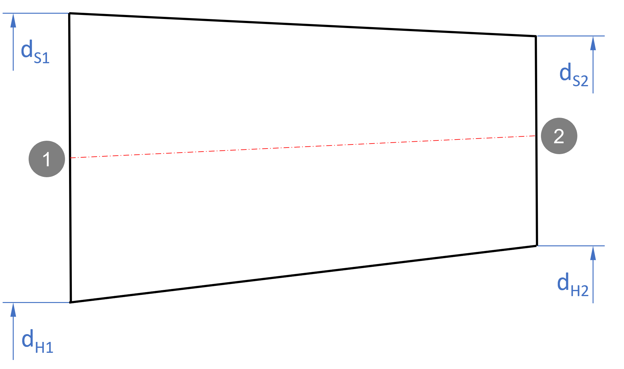
For dS2/dH2-calculation
Meridional velocity ratio cm2/cm1 |
|
||
|
strictly axial |
dH2 = dH1 and dS2 = dS1 |
|
|
const. at hub |
dH2 = dH1 |
|
|
const. at mid-span |
dM2 = dM1 |
|
|
const. at shroud |
dS2 = dS1 |
|
In the group Efficiency the following efficiencies need to be given:
Design relevant
•Rotor efficiency ηtt (total-total: pressure ratio πtt specified in global setup) or
•Rotor efficiency ηts (total-static: pressure ratio πts specified in global setup)
![]()
Information only
•Mechanical efficiency ηm
Internal and mechanical efficiency form the overall efficiency (coupling efficiency):
|
PQ: (isentropic) Rotor power PD: Power output (coupling/ driving power) |
The rotor efficiency (or blade efficiency) ηtt describes the energy losses within the turbine caused by friction and vorticity. Friction losses mainly originate from shear stresses in boundary layers. Vorticity losses are caused by turbulence and on the other hand by changes of flow cross section and flow direction which may lead to secondary flow, flow separation, wake behind blades etc.. The rotor efficiency is the ratio between the actual specific enthalpy difference and the ideal (isentropic) specific enthalpy difference at loss less transmission:
![]()
The mechanical efficiency mainly includes the friction losses in bearings and seals:
![]()
rising with impeller size.
In the right panel of the tab sheet Parameter some variables are displayed for Information:
actual Power PD |
PD = PQ·ηttSt |
Power loss PL |
PL = PQ - PD |
Flow Qt |
calculated with total density in the outlet:
|
Pressure ratio total-total |
|
Pressure ratio total-static |
|
Efficiency total-total |
ηtt |
Efficiency total-static |
ηts |
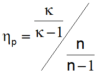
Polytropic efficiency |
(n .. polytropic exponent κ .. isentropic exponent) |
In general for cost reasons single-stage & single-intake machines are preferred covering a range of about 10 < nq < 400. If especially high specific speed values (nq > 400) do occur one can reduce rotational speed n or mass flow rate ṁ if feasible. Another option would be to operate several single-stage turbines - having a lower nq - in parallel.