|
<< Click to Display Table of Contents >> Parameters |
  
|
|
<< Click to Display Table of Contents >> Parameters |
|
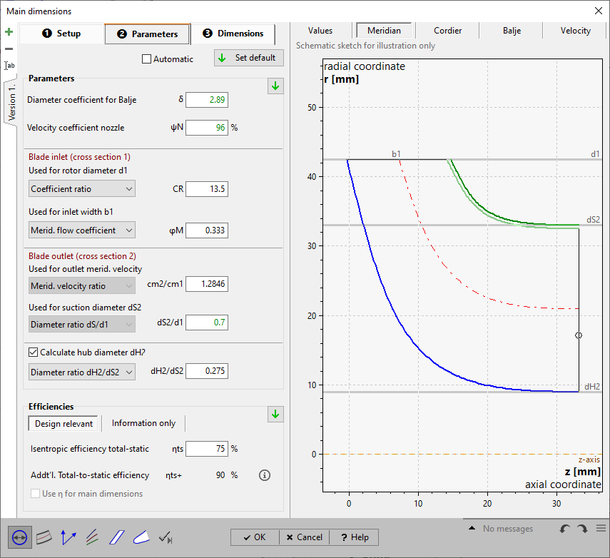
On page Parameters you have to put in or to modify parameters resulting from approximation functions in dependence on specific speed nq or flow rate Q.
See Approximation functions.
For details of how to handle the parameter edit fields please see Edit fields with empirical functions.
|
Parameter and efficiency values can be handled manually or can be switched to automatic update by the checkbox on top of the page. Then the default values are used always, even after design point modifications (see Global setup). |
If the automatic mode is not selected the current default values can be specified by one of the following options:
|
globally by the button on top of the page |
|
regionally by the default button within the Parameters or Efficiency region |
|
individually by the default button within the input field when selected |
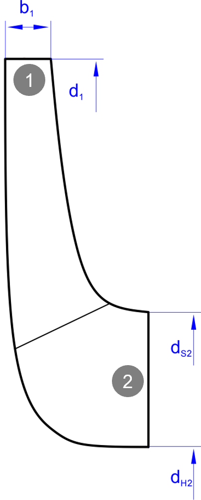
The panel Parameters allows defining alternative values in each case for the calculation of the following rotor main dimensions: •suction diameter dS2 •hub diameter dH2 •rotor diameter d1 •inlet width b1 |
|
For details of how to handle the parameter edit fields please see Edit fields with empirical functions.
The diameter coefficient is a parameter for the Balje diagram but not a design parameter. With its help suggestions for isentropic velocity ratio total-static νts as well as for the inlet width ratio b1/d1 can be get (only if total-to-static pressure ratio πts is specified, see global setup).
One of the following parameters has to be specified for the calculation of the rotor diameter d1.
Work coefficient ψ (= pressure and head coefficient) |
•dimensionless expression of the specific enthalpy
•big → small d1 •Guideline ~ 2 |
Flow coefficient φm |
▪dimensionless mass flow ▪in accordance to Cordier-Diagramm |
Tangential force coefficient ct = ψ/φm |
▪Coefficient of a flow force pointing in tangential direction 3 ... 4 Francis high-speed turbine 4 ... 8 Normal-speed turbine 8 ...10 Low-speed turbine
|
Coefficient ratio cR = ψ/φm2 |
▪Ratio of work to the square of the meridional speed 6 ...10 Francis high-speed turbine 10...12 Normal-speed turbine 12...30 Low-speed turbine
|
Isentropic velocity ratio total-static νts= u/c0 |
u: Peripheral velocity at inlet c0: spouting velocity
Defaults by Balje diagram (only if total-to-static pressure ratio πts is specified, see global setup) |
Between the work coefficient ψ, the relative flow angle β1 and the tangential force coefficient ψ/φm there is the following relation:
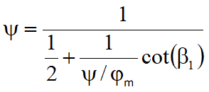
At a relative flow angle of β1= 90° the work coefficient becomes ψ = 2. In this case the work coefficient should not be chosen as a design parameter in the tab sheet Parameters. Otherwise one has no influence on the meridional flow coefficient and therefore meridional flow, see last equation.
One of the following parameters has to be specified for the calculation of the rotor inlet width b1.
Meridional flow coefficient φm= cm/u |
Default according to equation above:
|
Inlet width ratio b1/d1 |
Defaults by Balje diagram (only if total-to-static pressure ratio πts is specified, see global setup) |
For all further geometric variables guess values have to be given:
Diameter ratio d2/d1 |
~0.5 |
Meridional acceleration |
|
Meridional acceleration (suction side) cmS/cm2 Diameter ratio dS/d1 |
~0.7 |
Diameter ratio dH/dS |
~0.3 |
There are three modes for the definition of the hub diameter dH2:
•Direct input in the tab sheet Dimensions (check box "Calculate hub diameter" deactivated)
•Combo box option "Diameter ratio dH/dS": automatic calculation with dH2 = dH/dS * dS2.
•Combo box option "Diameter ratio d2/d1": automatic calculation with dH2 = dH/dS * dS. Here the diameter ratio dH/dS will be adjusted in a way that the guideline of the geometrical ratios will be met.
With option "diameter ratio dS/d1" for the dS2-calculation the option "Diameter ratio d2/d1" is not available.
In the group Efficiency the following efficiencies need to be given:
Design relevant
•Rotor efficiency ηtt (total-total: pressure ratio πtt specified in global setup) or
•Rotor efficiency ηts (total-static: pressure ratio πts specified in global setup)
Information only
•Mechanical efficiency ηm
Internal and mechanical efficiency form the overall efficiency (coupling efficiency):
|
PQ: (isentropic) Rotor power PD: Power output (coupling/ driving power) |
The rotor efficiency (or blade efficiency) ηtt describes the energy losses within the turbine caused by friction and vorticity. Friction losses mainly originate from shear stresses in boundary layers. Vorticity losses are caused by turbulence and on the other hand by changes of flow cross section and flow direction which may lead to secondary flow, flow separation, wake behind blades etc.. The rotor efficiency is the ratio between the actual specific work Y and the specific work at loss less transmission:
![]()
The mechanical efficiency mainly includes the friction losses in bearings and seals:
![]() (rising with impeller size)
(rising with impeller size)
If the check box "Use η for main dimensions" is set, then main dimension calculation is done on the basis of Δh=Δhis·η. Otherwise Δhis - the isentropic specific enthalpy - is used.
In the right panel of the tab sheet Parameter some variables are displayed for Information:
Actual Power PD |
PD = PQ·ηttSt |
Power loss PL |
PL = PQ - PD |
Flow Q |
calculated with total density in the outlet:
|
Total pressure inlet pt1 |
pt1 = π⋅pt2 |
Pressure ratio total-total |
|
Pressure ratio total-static |
|
Stage efficiency total-total |
ηttSt |
Isentropic efficiency total-static |
ηts |
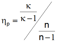
Polytropic efficiency |
(n .. polytropic exponent κ .. isentropic exponent) |
In general for cost reasons single-stage & single-intake machines are preferred covering a range of about 10 < nq < 400. In exceptional cases it may become necessary to design a rotor for extremely low specific speed values (nq < 10). These rotors are characterized by large rotor diameters and low rotor widths. The ratio of free flow cross section area to wetted surfaces becomes unfavorable and is causing high frictional losses. To prevent this one may increase either rotational speed n or mass flow rate ṁ if possible. An alternative solution could be the design of a multi-stage turbine reducing the pressure drop of a single-stage. If especially high specific speed values (nq > 400) do occur one can reduce rotational speed n or mass flow rate ṁ if feasible. Another option would be to operate several single-stage turbines - having a lower nq - in parallel.
Please note: CFturbo is preferably used between 10 < nq < 150 – radial and mixed-flow rotors.