|
<< Click to Display Table of Contents >> Additional views |
  
|
|
<< Click to Display Table of Contents >> Additional views |
  
|
The following information can be displayed in the meridional contour dialog using the "Additional views" button: |
|
Some additional values are displayed for information:
•Minimal curvature radius on hub and shroud (position is marked on the hub and shroud curves)
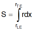
•Static moment S from leading to trailing edge on hub and shroud (see below)
•Angle ε in the hub and shroud end points measured to the horizontal direction
•Angle γLE of leading edge on hub and shroud measured to the horizontal direction
•Axial extension Δz of hub and shroud
•Radial extension Δr of hub and shroud
•Angle γTE of trailing edge measured to the horizontal direction
•Default axial extension ΔzD from inlet shroud to outlet midline (defined for centrifugal impellers only)
•Maximal axial extension ΔzM of complete meridional shape
•Maximal radial extension ΔrM of complete meridional shape
•Axial blade overlapping zB of shroud blade area onto hub blade area in z-direction
•LE distance b1 from LE at hub to LE at shroud
•LE circle b1 as diameter of a circle inside the meridional contour at LE position
•LE diameter d1 at intersection of LE and midline
•Diameter ratio d1/d2
•LE diameter d1ave as average of hub and shroud diameter at LE
3D model of the currently designed meridional shape.
|
The meridian contains hub and shroud as well as a circular projection of the blade in a plane. |
Curvature progression along hub and shroud curve. The progression should be as smooth as possible avoiding hard peaks.
The static moment is the integral of the curve length (x) in the blade area multiplied by the radius (r):

It should be similar for hub and shroud end points.
Progression of the cross section area between hub and shroud.
Local maximum or minimum should be avoided.
Progression of the meridional velocity cm along the meridional streamlines.