|
<< Click to Display Table of Contents >> Secondary flow path |
  
|
|
<< Click to Display Table of Contents >> Secondary flow path |
|
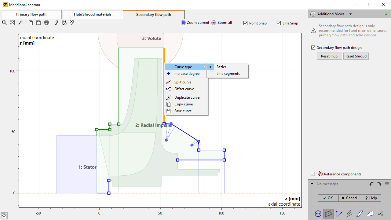
Secondary flow path for impellers can be designed by selecting the "Secondary flow path" page on top left and activate the feature on the right side. Initial contours will be visible, which can be manipulated using the control points and the context menu of the curve (see Hub/Shroud materials).
Endpoints of the "secondary flow path" on the material solid are constrained to the contour. Therefore, axial coordinate z and radial coordinate r cannot be modified independently.
After the model finishing the meridional primary and secondary flow paths are connected to a single solid geometry, "Flow domain".
Hub and Shroud casing can be designed by manipulating their meridional contours. The feature is available if the following prerequisites are fulfilled:
•Hub/Shroud materials must be activated for this impeller
•Neighboring static components have to exist
•An offset between impeller and neighboring components is required
Depending on settings of main dimensions, some parts of the contour can become inactive, e.g. for unshrouded impellers the shroud is already defined by primary flow path.
The secondary flow path is defining the real geometry. In contrast to this, a simplified virtual geometry can be specified and exported separately (see virtual geometry).
Problem |
Possible solution |
|---|---|
Missing static component at inlet/outlet. Both, upstream and downstream component to impeller are necessary. |
|
There has to be a component at the impeller's inlet/outlet for designing a Secondary flow path. |
Add a component to the impeller's inlet/outlet. |