|
<< Click to Display Table of Contents >> Hub, Shroud |
  
|
|
<< Click to Display Table of Contents >> Hub, Shroud |
|
There are two different options to define hub and shroud contours.
![]() Hub, Shroud Direct design of the two contours
Hub, Shroud Direct design of the two contours
![]() Middle Design of center line; the contours result from given cross section distribution between suction (dS) and outlet (d2) cross sections
Middle Design of center line; the contours result from given cross section distribution between suction (dS) and outlet (d2) cross sections
In the first case, hub and shroud can be designed separately.
In the second case, only the geometric center line of the flow channel will be modified. The contours result from specifying a relative cross section distribution. It may either be linear or could be loaded from a file using the Progression dialog.
The first value of each line is the relative meridional coordinate x along the center line, with x=0 at the inlet cross-section and x=1 at the outlet cross-section. The second value is the relative cross section Arel, which allows to compute the related absolute value:
![]()
The cross section is used to determine the meridional width b vertical to the flow direction.
This strategy is mainly suitable for mixed-flow impellers, it's suboptimal for centrifugal impellers with relative sharp direction change from axial to radial.
The axial start position as well as the axial extension of the meridional shape can be specified in the Axial dimensions area on the right. Both can also be modified interactively in the graphics.
Contour curves can be designed as:
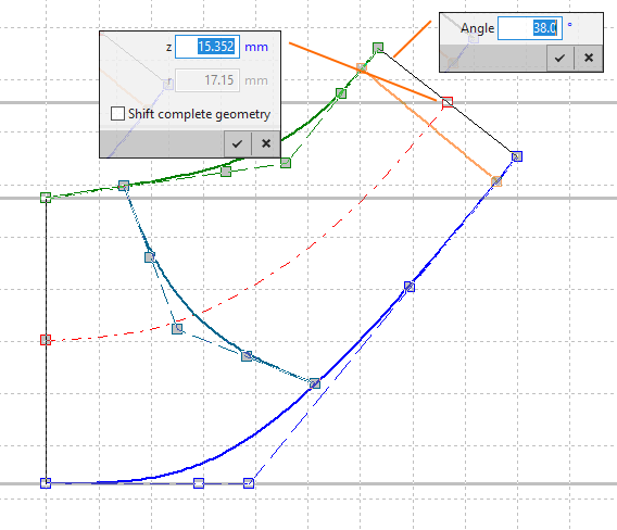
•Bezier curve
The curve is defined by the position of the Bezier points.
¢ Details
•Circular Arc + Straight line
The curve consists of a circular arc and a straight line.
¢ Details
•Straight line
The contour is defined by a straight line between start and endpoint.
•Polyline
The curve is fixed and cannot be modified interactively. Import of point sets from file is possible (Load polyline). Note, imported point sets are re-sampled on an interpolating cubic spline using 100 points. This may lead to deviations to original polyline, especially in case of low point counts.
Centrifugal fan impellers are designed simply by arc and line by default (Circular Arc + Straight line), all other impeller types in Bezier mode (Bezier curve).
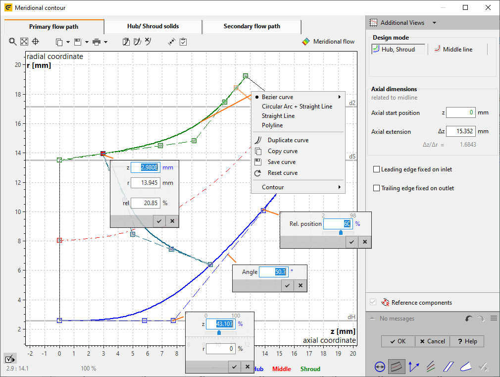
On the endpoints of hub and shroud the complete geometry can be shifted optionally (Shift complete geometry). Hence the geometry can be positioned on a specific axial position.