|
<< Click to Display Table of Contents >> Bezier |
  
|
|
<< Click to Display Table of Contents >> Bezier |
|
Hub and Shroud are represented by 4th order Bezier curves. This is the default and most flexible curve mode.
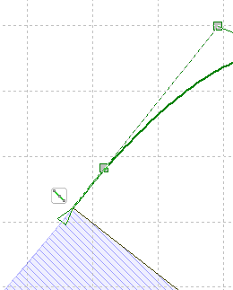
The curve is determined by five Bezier points.
Points 0 and 4 are defining the endpoints of the curves while the other three points determining the shape of the curve. The middle point (2) can be moved without any restrictions whereas points 1 and 3 have only one degree of freedom. Point 1 is only movable on the straight line between points 0 and 2, point 3 between point 2 and 4. Therefore no curvature is occurring at the end of the curves. In conjunction with a continuous curvature gradient small velocity gradients can be expected. The two straight lines are defining the gradients in the end points of the curves.
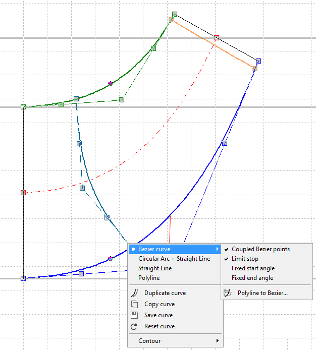
Bezier point 2 can be limited in its mobility by the curve context menu option Limit stop. As a result the axial and radial position is limited in the area between the curve endpoints 0 and 4.
The above mentioned coupling between the Bezier points can be switched on or off by the curve context menu option Coupled Bezier points.
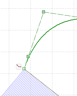
Start angle (line 0-1 or 0-1-2) and end angle (line 3-4 or 2-3-4) can be fixed optionally by the curve context menu option Fixed start angle or Fixed end angle. A fixed angle is illustrated by a dotted line instead a dashed one and by a triangular marker on the curve endpoint.
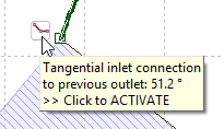
In Bezier mode a tangential connection to neighboring components (impeller or stator) can be switched on or off using the icon beside the the first or last Bezier point:
|
|
|
The hint of the icon contains the angle of the neighboring component for information. |
For an automatic primary design of the contours the following values are used:
▪Main dimensions: dH, dS, d2, b2
▪Inclination angle g of trailing edge to horizontal (see Approximation functions)
▪Inclination angle e of hub and shroud to vertical (see Approximation functions)
▪Axial extension: pumps, fans according to a) (Guelich), turbines according to b) (Lindner), compressor according to c) (Aungier). In some cases where the hub diameter dH is quite small compared to the impeller diameter d2, for compressors the average of a) and b) is applied instead of c).
![]()
![]()
![]()
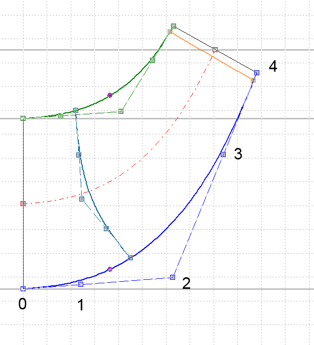
Point 1 is primary placed at 3/4 of the axial distance of points 0 and 2, point 3 at 2/3 of the radial distance of points 2 and 4.
The manipulation of the contours can be achieved by shifting the positions of the Bezier points. As an alternative the position of Bezier points can be realized by input of numerical values (see Graphical dialogs). Trailing edge can be rotated by moving Bezier points 4. If <Ctrl> key is pressed simultaneously the whole trailing edge can be moved in axial direction with constant inclination angle (change axial extension). Inclination angle of trailing edge can be numerically determined by clicking the right mouse button on it.
In the design process for the meridional contours the user should try to create curvatures which are as steady as possible in order to minimize local decelerations. The maximum values of the curvature should be as low as possible and should entirely disappear at the end of the contours. These requirements are met very well by Bezier curves showing the above mentioned limitations. Local cross section 2πrb should grow from the suction to the impeller diameter as uniformly as possible.
If using simple polyline for hub and/or shroud - e.g. for imported meridional geometrie - this curve can be converted to a Bezier curve. Thus, it's possible to make systematic modifications of existing geometries.