|
<< Click to Display Table of Contents >> Setup |
  
|
|
<< Click to Display Table of Contents >> Setup |
|
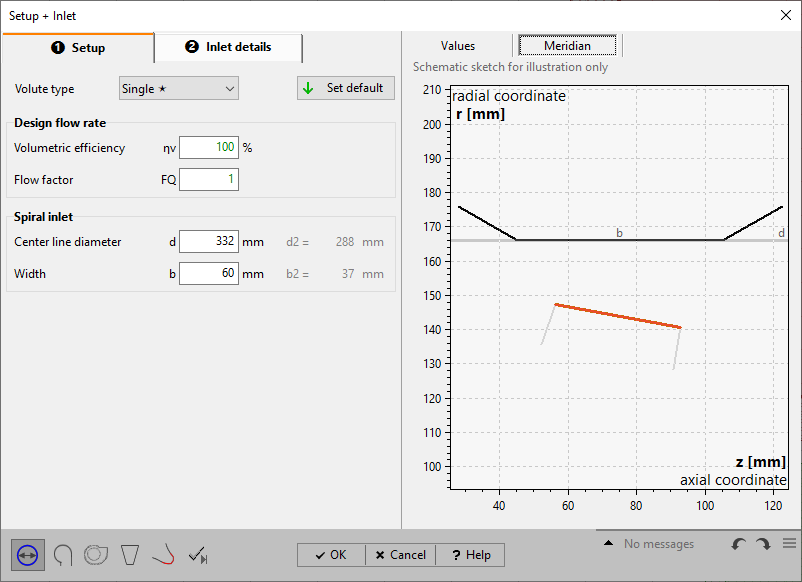
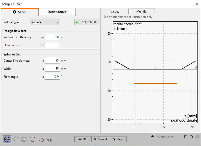
On page Setup you can define some general properties used for the spiral design.
Depending on the project type and/ or position in project, different input parameters are required (see below). Outlet volute [typical for centrifugal pumps, fans, compressors]
|
Inlet volute [typical for radial inflow turbines]
|
Volute type
•Single volute (default)
This simple type is commonly used and has a single cut-water.
•Double volute
A second cut-water (splitter) is designed in order to reduce the radial forces.
Design flow rate
•Volumetric efficiency ηv (default: 1.0)
to consider any internal volumetric losses (recirculation)
•Flow factor FQ (default: 1.0)
for over dimensioning, particularly for better efficiency at overload operation
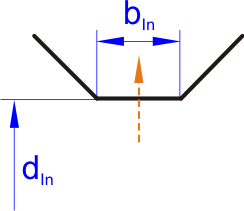
Spiral inlet (outlet for turbines) •Inlet diameter dIn (d4) •Inlet width bIn (b4) •Abs. flow angle α4 (turbines) •Automatic update from interface to apply changes from neighbor components |
|
Please note:
For stand-alone volutes you have to define the inlet interface first, see Inlet Details, instead of specifying dIn and bIn values.
[for pumps, fans, compressors]
dIn and bIn are suitable to the previous component outlet. If the previous component is an impeller d4 and b4 are determined using the ratios d4/d2 and b4/b2, which are calculated from functions dependent on the specific speed nq (see Approximation function).
Clicking on the Set Default button at top recalculates the standard values.
A short distance between the impeller and the cut-water is desirable for reasons of flow. For acoustic and vibration reasons, however, a certain minimum distance is necessary. The inlet width bIn should be chosen such that the width/height ratio at the end cross-section of the volute is close to 1. The ratio b4/b2 can be varied within a relatively wide range without significant negative effect on the efficiency. For centrifugal impellers with open impeller sides, values up to b4/b2=2 are possible. At higher specific speeds (wider impellers), however, high width ratios have a negative effect on flow (intensive secondary flows, turbulence losses). In this case, b4/b2 should be between 1.05 and 1.2.
Values dIn and bIn are coupled to the corresponding interface values.
[for turbines]
dOut and bOut has to be set by the user.
Various calculated values are shown, for information purposes, on the right side (Values):
Calculated internal flow rate Qi |
|
Inlet/Outlet diameter ratio |
dIn/d2 |
Inlet/Outlet width ratio |
bIn/b2 |
Inlet/Outlet meridional velocity |
cm |
Inlet/Outlet circumferential velocity |
cu |
Inlet/Outlet velocity |
c |
Inlet/Outlet flow angle |
α |
[for compressors, turbines]
Static pressure |
p |
Temperature |
T |
Density |
ρ |
Mach Number |
Ma |
Problem |
Possible solutions |
|---|---|
Swirl-free inflow is implausible for volute designs. |
|
The volute is the first component of the project and the inflow swirl is defined by the Global setup. With swirl-free inflow a volute calculation will be impossible. |
Adapt pre-swirl in the Global setup |
Thermodynamic state could not be calculated. |
|
For the chosen configuration of global setup, precursor component and spiral dimensions a reasonable thermodynamic state cannot be calculated. Then an automatic velocity based contour design will not be possible since the necessary values of cu4 and Qi are not available. |
e.g. reduce the mass flow or increase the cross section |
Pressure and temperature not within the liquid phase of the fluid. |
|
If the fluid model = CoolProp, fluid properties will be calculated as function of pressure and temperature. In case the local pressure and temperature are not above the vapor pressure curve, the fluid state is not valid. |
Increase dimensions (width, diameter) or change Global setup (e.g., decrease mass flow, increase pressure, decrease temperature). |