|
<< Click to Display Table of Contents >> Reverse Engineering |
  
|
|
<< Click to Display Table of Contents >> Reverse Engineering |
|
Reverse Engineering (RE) is the process transforming 3D geometry from neutral file formats (STEP, IGES, Parasolid, BREP) into a parametric CFturbo model.
The process is semi-automatic and consists of the following basic stages:
1.Creating/opening a CFturbo-project considering the desired machine type
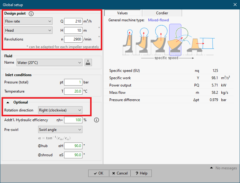
2.Specifying the design point (Global setup)
3.Defining 3D geometry to be redesigned
4.Specifying parameters for automatic computation of the CFturbo model
5.Manual adjusting the CFturbo model to improve alignment with the initial 3D geometry
The stages 1. and 2. serve the purpose of specifying the turbomachinery's operating point as usual. The stages 3. and 4. are performed inside a separate dialog enabling the user to create a CFturbo model quickly and efficiently. In stage 5. the user can modify the redesigned CFturbo-model as needed within the ordinary design process (impellers, stators).
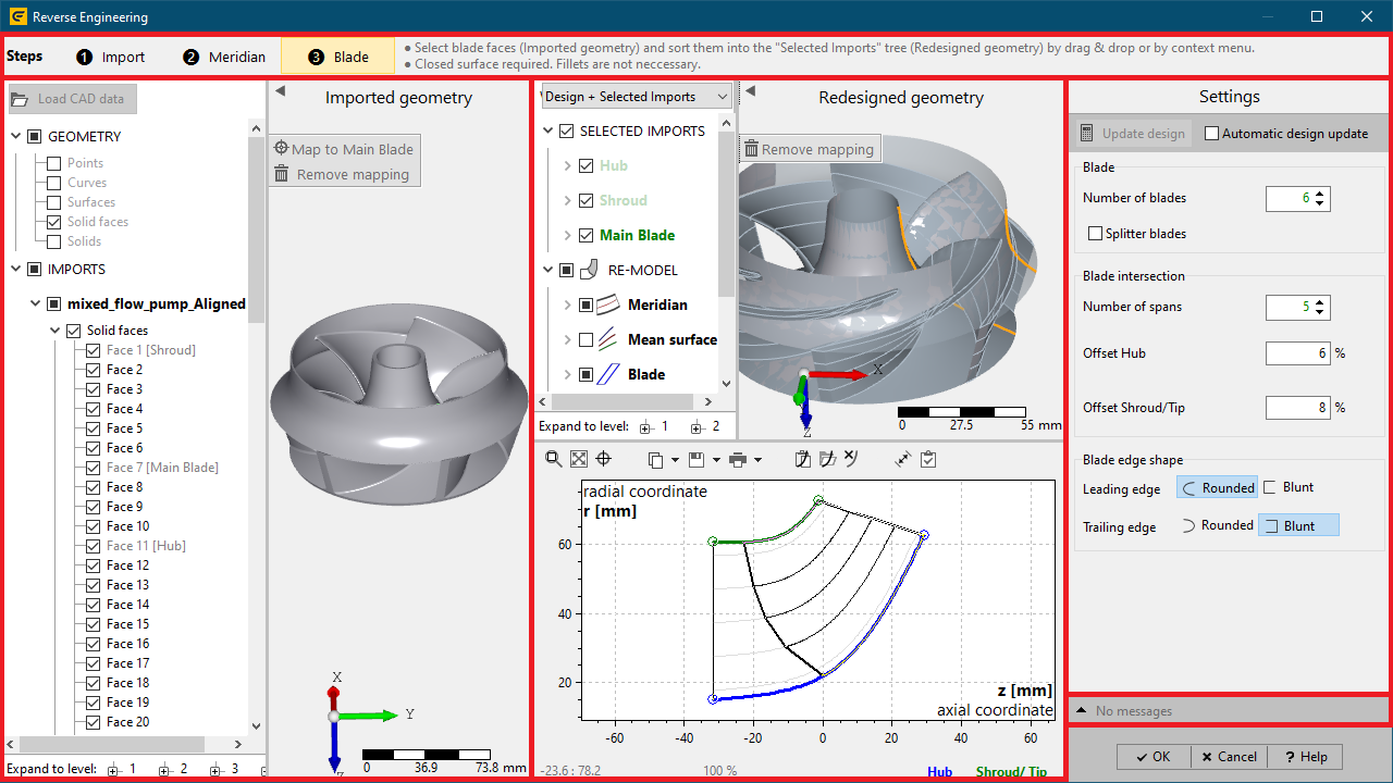
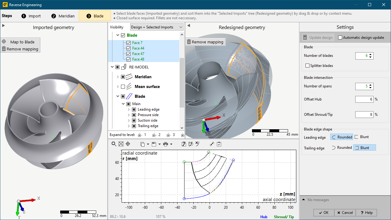
The RE-dialog is divided into the following parts:
1.Steps (top)
•selecting the current active RE-step (loading 3D geometry, meridional redesign, blade redesign)
•contains information related to the current step
2.Imported geometry (left)
•loading external 3D geometry
•displaying the imported 3D geometry
•aligning geometry to 3D coordinate system of CFturbo model
•specifying CFturbo semantics for related geometry-elements (e. g. hub, shroud, blade)
3.Redesigned geometry (middle)
•presenting computation results of the CFturbo model as 3D geometry and meridional view
•specifying parameters for computation of the CFturbo model via 2D contour's context menu inside meridional view
4.Settings (right)
•specifying parameters for computation of the CFturbo model
5.Message tree (bottom right)
•contains information, warnings and errors occurred during the RE-process
•Creating/opening a CFturbo-project considering the desired machine type
•Within Global setup: Specifying the design point suitable for the model to be redesigned
2. Load external 3D geometry
•Preconditions:
oRE-step Import must be selected at the top
oinput geometry must be represented by parametric surface data
(e. g. B-Spline surface, Cylindrical surface, etc.)
oinput geometry can be defined within a single or multiple files representing neutral file formats STEP, IGES, Parasolid or BREP
•Load geometry by clicking Load CAD data button or via drag & drop from a file explorer into the 3D-view.
•Loaded geometry is displayed in the 3D view and contained geometry elements are listed in the model tree left.
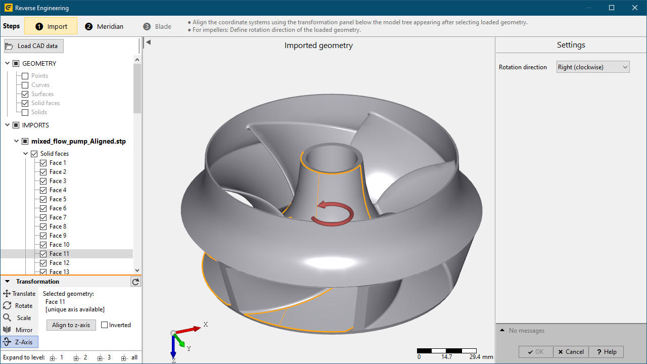
3. 3D alignment of loaded 3D geometry
•In order to obtain an accurate CFturbo model the loaded geometry has to be aligned sufficiently to the 3D coordinate system of the CFturbo-model.
•This essentially includes aligning rotation/symmetry axis of loaded geometry with the z-axis of the global coordinate system.
•Achieving a valid alignment can directly be done inside the Imported geometry section using Transformation panel.
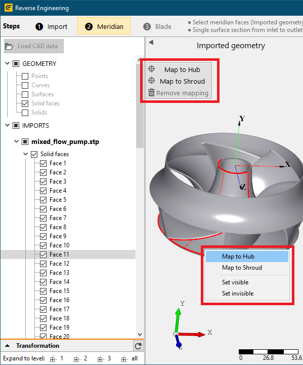
4. Defining CFturbo-semantics on geometry elements
•In order to compute a CFturbo model from external 3D geometry a classification of imported 3D faces representing a specific CFturbo model part (e. g. hub, shroud, blade) must be applied (mapping).
•Mappings are applied context sensitive related to the currently selected RE-step (Meridian: Hub, Shroud/Tip, Blade: Main blade, Splitter blade) at the top.
•This can be achieved by selecting a single or multiple 3D face(s) in the 3D view or model tree and using one of the following options:
oopening the context menu by clicking right mouse button and selecting an appropriate CFturbo model part (see first image below)
oclicking buttons representing CFturbo model parts next to the model tree (see first image below)
•Mappings of 3D face(s) to CFturbo-model parts are represented by an information in the model tree of the Imported geometry section and by explicit nodes in the model tree of the Redesigned geometry section.
•Mappings can be deleted using one of the following options:
oopening the context menu of the related tree node in the Redesigned geometry section and choosing the option Remove mapping
oclicking button Remove mapping next to the model tree
5. Computation of CFturbo model
•Updating redesigned model:
owithin RE-step Meridian: computation of the CFturbo model is performed automatically related to user inputs
owithin RE-step Blade: computation of the CFturbo model is started manually by pressing Update design in the Settings section or is performed automatically related to user inputs in case of activated Automatic design update
oAutomatic computations are triggered by adding/removing assignments of 3D-faces to CFturbo model parts and by changing parameters in the Settings section and in the context menu of 2D meridional contours
•Parameters:
RE-step |
Parameter |
Description |
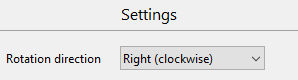
Import |
Rotation direction |
Defines impeller's rotation direction
|
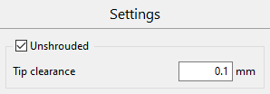
Meridian |
Unshrouded |
Closed (shrouded) or open (unshrouded) geometry at blade tip side
|
Tip clearance |
Gap between blade tip and casing |
|
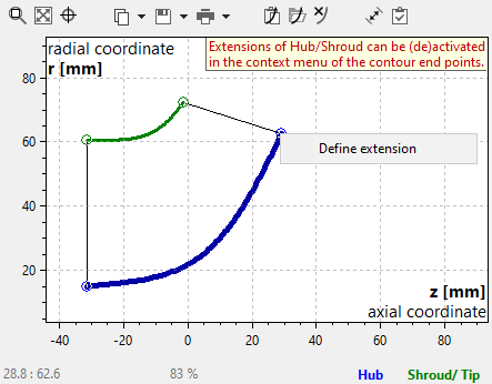
Define extension |
Hub/Shroud can be extended to user-defined z,r coordinates at the inlet/outlet. This can be applied in case the user-defined 3D-geometry of Hub/Shroud results in too short contours in order to obtain a valid Meridian.
|
|
Remove extension |
Removes user-defined Hub/Shroud extension at the inlet/outlet. |
|
With blades [Stator only] |
Definition of a vaned or vaneless stator |
|
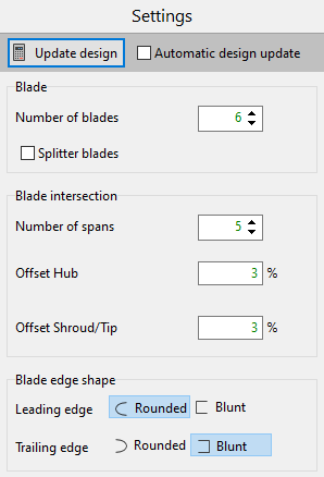
Blade |
Number of blades |
Defines the number of blades of the CFturbo model. |
Splitter blades |
Defines whether geometry has splitter blades. |
|
Number of spans |
Defines number of intersections of the user-defined blade geometry used for blade profile computation. |
|
Offset Hub/Shroud/Tip |
Blade intersections are evenly distributed between Hub and Shroud. The area of intersections can be limited by offsets on Hub- and on Shroud-/Tip-side in order to avoid inaccurate blade profiles due to blade root fillets. Suggestion: Remove blade root fillets from initial CAD-data, if possible. |
|
Blade edge shape (Leading/Trailing edge) |
Defines the shape of the Leading/Trailing edge of the user-defined blade geometry (blade profile computation depends on shape of blade's Leading/Trailing edge). |
•Results of computations are displayed inside the Redesigned geometry section:
o2D contours in z,r coordinate system inside 2D meridional view:
▪Hub / Shroud / Tip contours
▪Blade's Leading / Trailing edge
▪Spans (light grey: contours for blade intersection; black: valid blade intersection; orange: invalid blade intersection)
o3D design model in the 3D-view (incl. model tree)
oIndication of validity of user-defined input geometry assigned to CFturbo model parts by model tree node color
(green: valid, red: invalid/incomplete)
oWarnings/Errors during computation inside the message list bottom right
6. Finalization of import process
•After computation of a valid CFturbo model the Reverse engineering dialog can be closed by pressing OK button (irreversible)
•Now the CFturbo project contains the new component which has to be activated finally
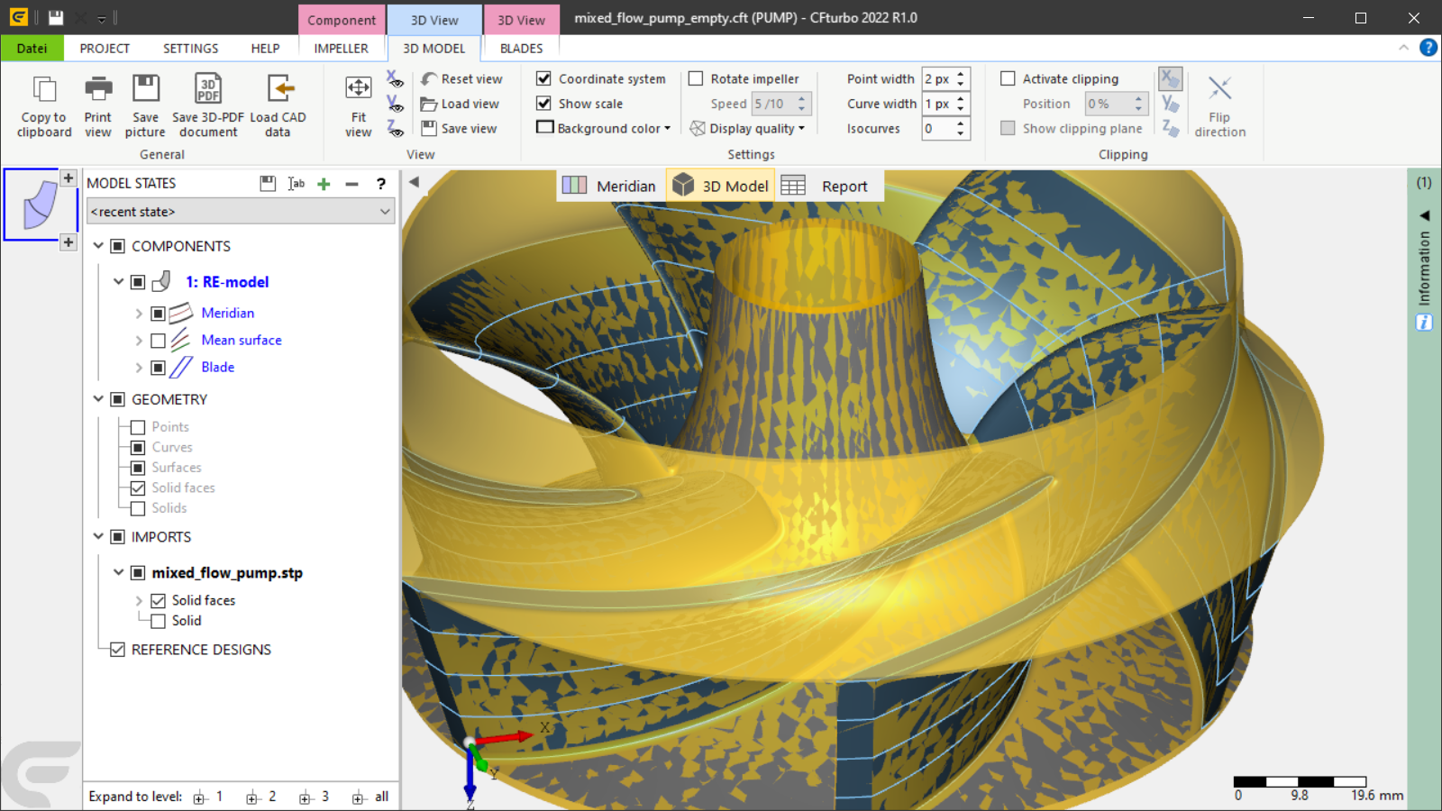
In this section the RE-process from initial input geometry to a CFturbo design is documented for a mixed-flow pump exemplarily. Any redesigned CFturbo model can further be modified as needed inside the ordinary design process.
•Creating a new CFturbo-project

•Specifying the design point within Global setup
•Adding a new component and specifying the import-format
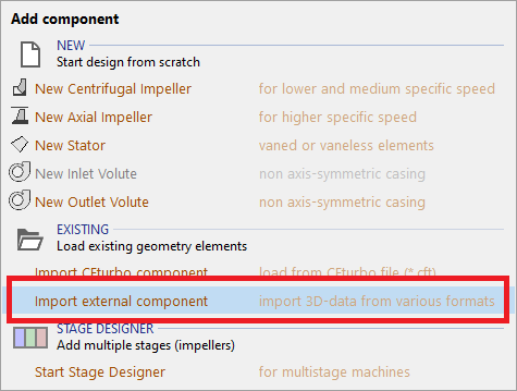
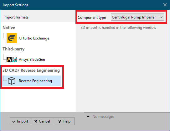
2. Loading and preparing external 3D geometry
•load external 3D geometry from neutral 3D file formats
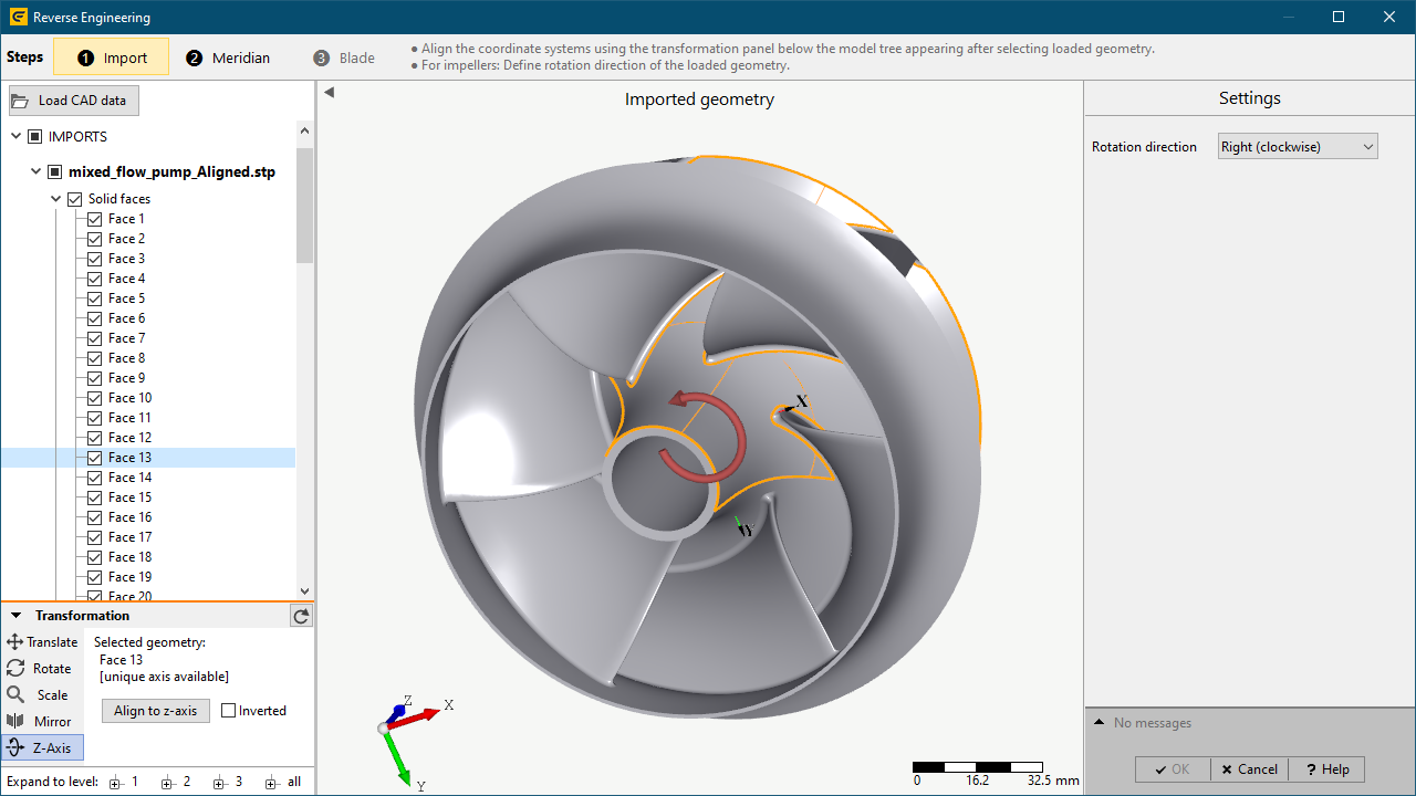
•align loaded geometry with the coordinate system of the CFturbo model
ocollinear alignment of rotation axis with the z-axis
ofluid flow direction in positive z-axis direction (for turbines: opposite direction!)
•define desired rotation direction of the loaded geometry
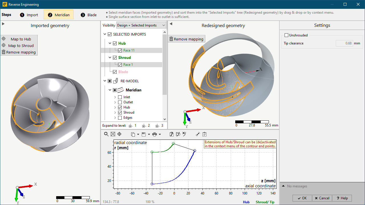
3. Meridional redesign
•Selection of Step ❷ Meridian
•Map 3D-faces to Hub / Shroud
•It's not necessary to select all 3D-faces representing the complete hub-/shroud-surface. Instead a single face covering the surface from inlet to outlet is sufficient.
4. Blade redesign
•Selection of Step ❸ Blade
•Map 3D-faces of a single blade to Blade
•select the Blade edge shape of the loaded blade geometry (Rounded, Blunt)
•choose sufficient Blade intersection parameters
odefault Number of spans is sufficient in general
ooffsets can be increased in case of large blade root fillets (optional)
•press Update design in order to compute the redesigned geometry
5. Finalization
•close RE-dialog by pressing OK after a valid design model is computed
(initially opened/created project now contains the redesigned CFturbo-model)
•activate the redesigned component (in order to modify the design)
•save the created design by saving the project
Problem |
Possible solutions |
|---|---|
Hub / Shroud: Rotation axis not collinear with global z-axis for [faces]. |
|
3D-alignment of specified Hub/Shroud faces is inaccurate. Symmetry axis is not collinear with global z-axis. |
Update 3D-transformation of imported geometry by aligning symmetry axis to global z-axis. |
Hub / Shroud: No rotation axis information available for [faces]. |
|
The specified Hub/Shroud faces contain no information about a symmetry axis, which can be used to align the geometry with global z-axis. Insufficient alignment with global z-axis can result in erroneous meridional contours. |
In case of erroneous meridional contours improve alignment ensuring symmetry axis being collinear with global z-axis. |
Calculation of following blade profile(s) failed: [span number(s)]. |
|
Cutting selected blade faces by span surfaces results in open blade profile(s). Redesigned blade shape may differ significantly from given blade faces. |
Ensure there are no gaps between specified blade faces in the range of span surfaces. Improve redesigned blade shape manually in the ordinary design process after finishing the RE-process. |
M-distribution of following meanline(s) is not strictly increasing: [span number(s)]. |
|
Unsupported meanline shape (no strictly increasing m-distribution in m,t-coordinate system). Redesigned blade shape may differ significantly from given blade faces. |
Improve redesigned blade shape manually in the ordinary design process after finishing the RE-process. |
Hub / Shroud / Blade tip is invalid. |
|
A valid 2D meridional contour couldn't be computed from given 3D-faces (e. g. self-intersections). |
Ensure all specified faces represent the Hub / Shroud / Blade tip of the model. Ensure correct 3D-alignment of specified faces with the global coordinate system of the CFturbo model. Reduce tip clearance. Adjust defined extensions of hub/shroud contours. |
Primary flow path could not be computed. |
|
A valid 2D meridional flow path couldn't be computed from given 3D-faces |
Ensure specified faces for Hub and for Shroud/ Blade tip are not connected and do not intersect each other. Ensure all specified faces represent the Hub / Shroud / Blade tip of the model. Apply or adjust extensions of hub/shroud contours. |
Computing spans for blade surface intersection failed. |
|
Span surfaces used for blade surface intersection could not be computed from given hub and shroud/tip contours. |
Ensure no undulations are present in hub and in shroud/tip contours due to insufficient input geometry or insufficient 3D-alignment. |
Calculation of blade profiles failed. |
|
A redesigned blade could not be computed due to too less successfully computed blade profiles (at least two valid blade profiles must be available). |
Ensure there are no gaps between specified blade faces in the range of span surfaces. Ensure all specified faces represent the Main/Splitter blade of the model. Ensure blade does not exceed meridional boundaries. |
Unconnected blade faces selected. |
|
There are blade faces specified not being connected to others. |
Ensure specified blade faces are connected to each other. |